1. Loop 1
2. Loop 2
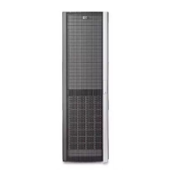
Figure 17 0C6D expansion rack for the EVA6400
.
1. Using 0.41m Fiber Channel copper cables, connect the disk enclosures in the first loop:
a. Connect P2 (I/O-A) on S-7 to P1 (I/O-A) on S-8.
b. Connect P2 (I/O-A) on S-8 to P1 (I/O-A) on S-9.
c. Connect P2 (I/O-B) on S-7 to P1 (I/O-B) on S-8.
d. Connect P2 (I/O-B) on S-8 to P1 (I/O-B) on S-9.
2. Using 0.41m Fiber Channel copper cables, connect the disk enclosures in the second loop:
a. Connect P2 (I/O-A) on S-10 to P1 (I/O-A) on S-11.
b. Connect P2 (I/O-A) on S-11 to P1 (I/O-A) on S-12.
c. Connect P2 (I/O-B) on S-10 to P1 (I/O-B) on S-11.
d. Connect P2 (I/O-B) on S-11 to P1 (I/O-B) on S-12.
3. Connect the rack power distribution units to a power source.
4. Using a power cord provided in your kit, plug one end into a disk enclosure power supply and
the other end into a rack power distribution module. Plug the left power supply into the left module
and the right power supply into the right module.
5. Repeat Step 4 for each disk enclosure in the expansion rack.
6. Power on the rack distribution units.
Installing disk enclosures into the expansion rack22

 Loading...


