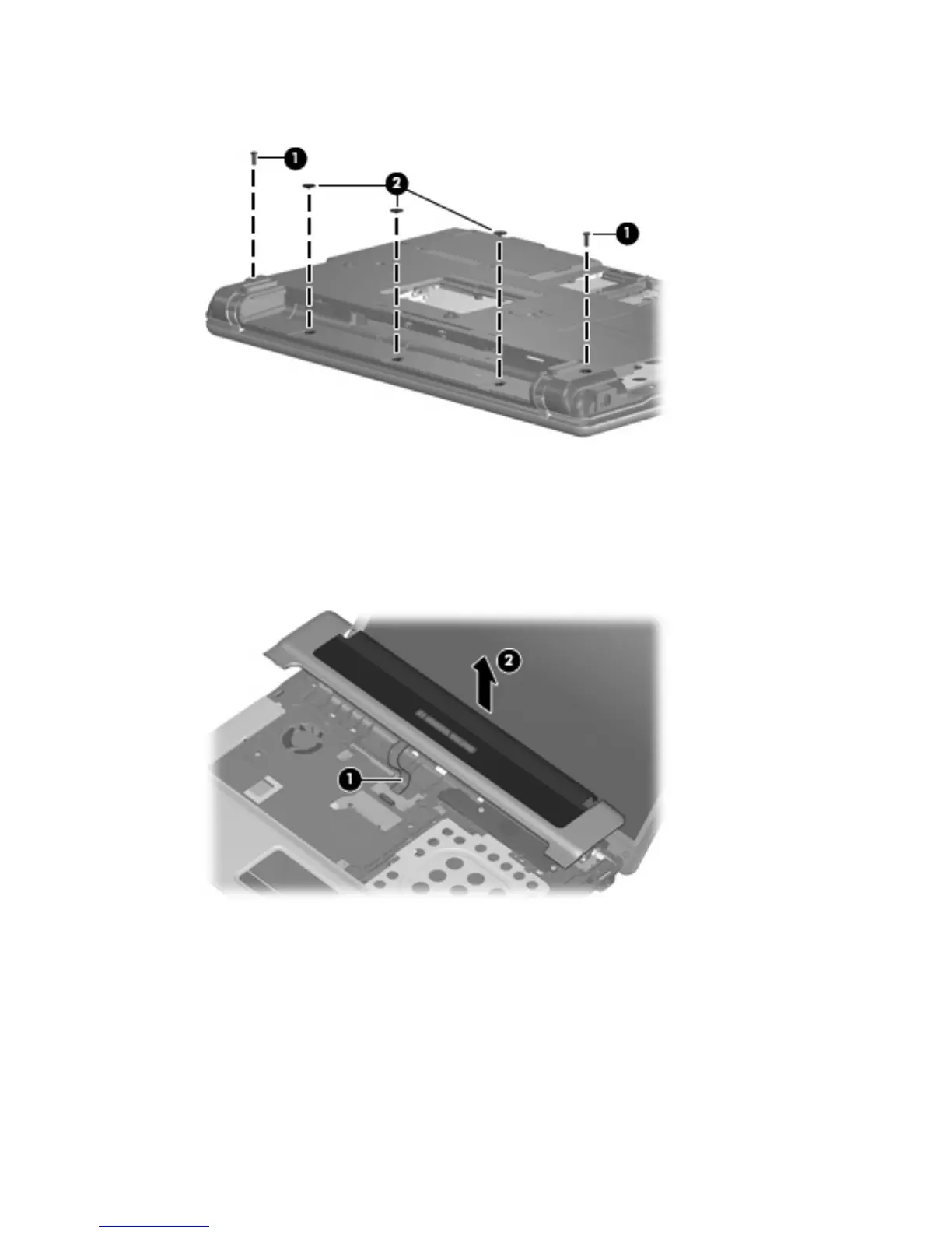
2. Remove the two Torx T8M2.5×9.0 screws (1) and the three Torx T8M2.5×3.0 broad-head
screws (2) that secure the switch cover to the computer.
3.
Turn the computer right-side up, with the front toward you.
4.
Open the computer as far as possible.
5. Release the ZIF connector to which the button board cable (1) is attached, and disconnect the cable
from the system board.
6. Remove the switch cover (2) by lifting it straight up.
Reverse this procedure to install the switch cover.
Component replacement procedures 49