3.
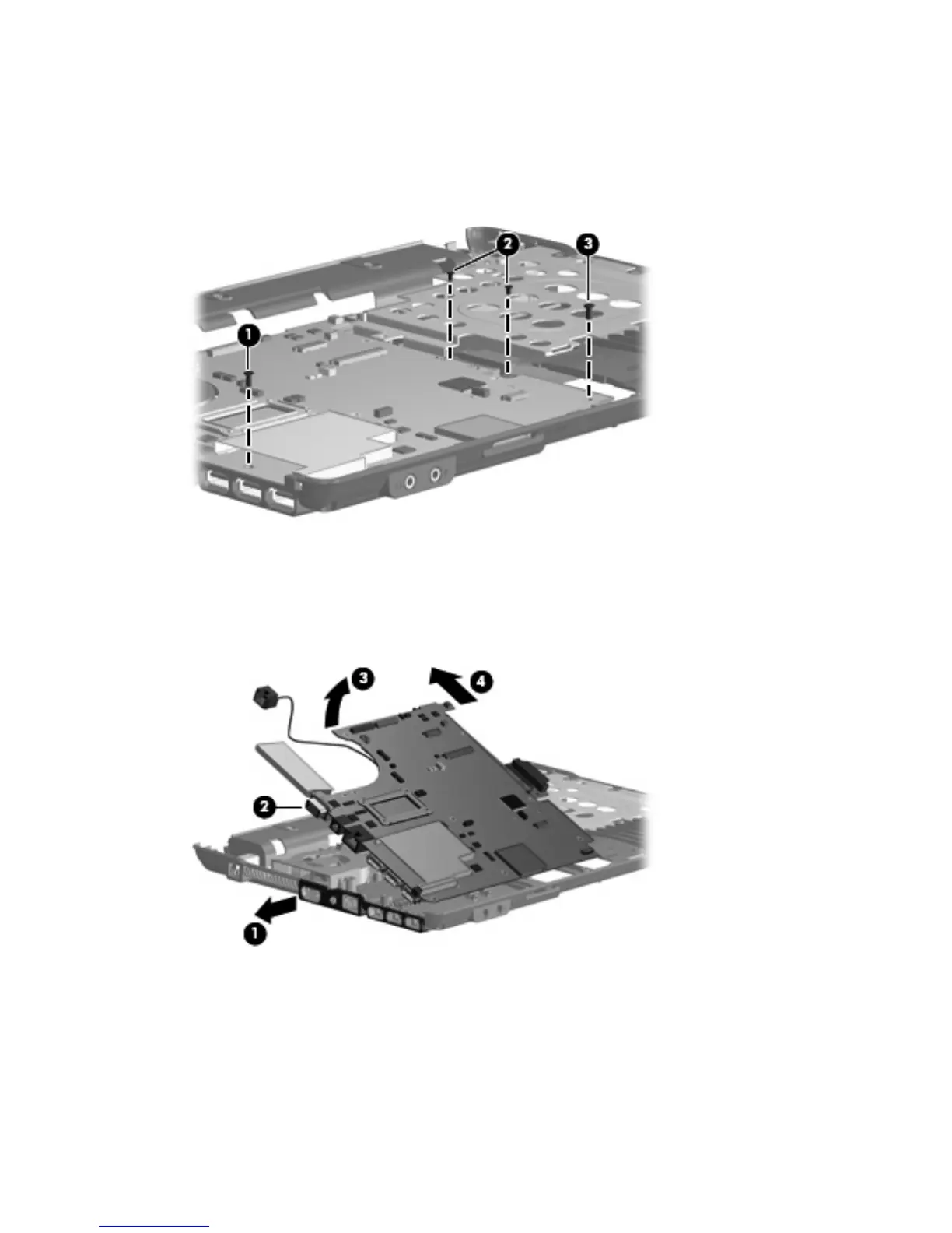
Remove the following screws:
(1) One Phillips PM2.0×6.0 screw
(2) Two Torx T8M2.0×4.0 screws
(3) One Torx T8M2.5×4.0 screw
4. Flex the left side of the base enclosure (1) until the external monitor connector (2) is clear of the
opening in the base enclosure.
5. Lift the rear edge of the system board (3) until it rests at an angle.
6. Remove the system board (4) from the base enclosure by sliding it back.
64 Chapter 4 Removal and replacement procedures