Operation
Model 8642A/B
Modulation,
FM
(cont'd)
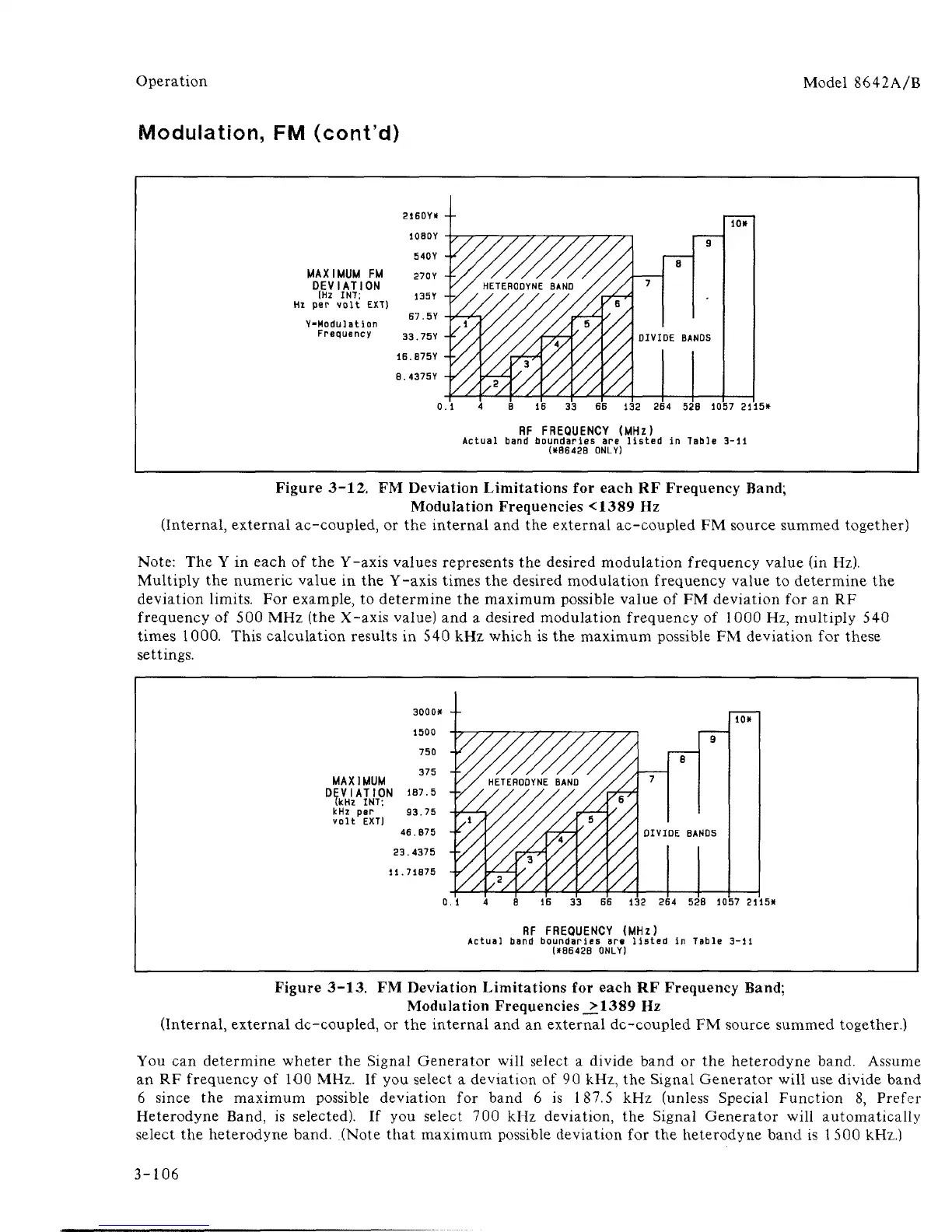
MAXIMUM FM
DEVIATION
[Hz
INT;
Hz
per
volt
EXT)
Y-Modulation
Frequency
DIVIDE BANDS
132
264 528 10
57 2115*
RF FREQUENCY (MHz)
Actual band boundaries
are
listed
in
Table
3-11
(*B642B ONLY)
Figure 3-12, FM Deviation Limitations
for
each
RF
Frequency Band;
Modulation Frequencies <1389
Hz
(Internal, external ac-coupled,
or the
internal
and the
external ac-coupled
FM
source summed together)
Note:
The Y in
each
of the
Y-axis values represents
the
desired modulation frequency value
(in
Hz).
Multiply
the
numeric value
in the
Y-axis times
the
desired modulation frequency value
to
determine
the
deviation limits.
For
example,
to
determine
the
maximum possible value
of FM
deviation
for an RF
frequency
of 500
MHz (the X-axis value)
and a
desired modulation frequency
of
1000 Hz, multiply
540
times 1000. This calculation results
in
540 kHz which
is the
maximum possible
FM
deviation
for
these
settings.
3000K
1500
750
375
-f
MAXIMUM
DEVIATION 1B7.5 -[?
(kHz
INT;
kHz
per
93.75
volt
EXT)
46.B75
23.4375
+,
11.71875
0.
1
57 2115*
RF FREQUENCY (MHz)
Actual band boundaries
are
listed
in
Table
3-11
1*86428 ONLY)
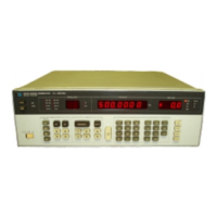
Figure 3-13. FM Deviation Limitations
for
each
RF
Frequency Band;
Modulation Frequencies _>1389
Hz
(Internal, external dc-coupled,
or the
internal
and an
external dc-coupled
FM
source summed together.)
You
can
determine wheter
the
Signal Generator will select
a
divide band
or the
heterodyne band. Assume
an
RF
frequency
of
1O0 MHz.
If you
select
a
deviation
of 90
kHz,
the
Signal Generator will use divide band
6 since
the
maximum possible deviation
for
band
6 is 187.5 kHz
(unless Special Function
8,
Prefer
Heterodyne Band,
is
selected).
If you
select
700 kHz
deviation,
the
Signal Generator will automatically
select
the
heterodyne band. (Note that maximum possible deviation
for the
heterodyne band
is
1
500 kHz.)
3-106


 To Next Page