Performance Tests
Model 8642A/B
PERFORMANCE TESTS
4-6.
HARMONICS TESTS
SPECIFICATION:
Electrical Characteristics
Harmonics
Sub-harmonics
Performance Limits
-20 dBc
-25 dBc
-30 dBc
none
-45 dBc
Conditions
<+16 dBm
<+10 dBm, band 10
<+10 dBm, band HET-9
band HET-9
bandl0
DESCRIPTION:
The HP 8642's frequency is set to values where harmonic performance
problems are most likely to be observed. The measuring receiver is used to
measure the power level at the harmonic or sub-harmonic frequency. To do
this,
the measuring receiver must have been calibrated over the full power
measurement range at that frequency. Doing the Level Accuracy
Performance Test automatically does this.
For troubleshooting purposes or characterization of other RF frequencies, a
spectrum analyzer may be used.
nan
□ a □
□ □
oo □□□
I
□ □
□ a
□ a
DD
□ DC
□
□I
□
□I
nnc
3DO
5DD
□ a
O
In
a
o®
HP 8642A/B
SYNTHESIZED
SIGNAL GENERATOR
10
MHz
OUTPUT
JRF
I
OUTPUT
BEF
EXT
INPUT
SENSOR
MODULE
MEASURING
RECEIVER
RF
INPUT
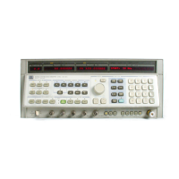
Figure 4-2. Harmonics Test Setup
EQUIPMENT: Measuring Receiver HP8902A
Sensor Module HP11722A
PROCEDURE:
la. Setup
Connect the instruments as shown in Figure 4-2. Preset the
instruments. Set the measuring receiver to tuned RF Level mode. If
the Level Accuracy Performance Test has just been done with the
same measuring receiver then continue with step 2. If Level
Accuracy has not yet been done or you have changed measuring
receivers then calibration is required. In this case, complete step lb
before continuing with step 2.
4-12


 To Next Page