Model 8642A/B Performance Tests
PERFORMANCE TESTS
4-10. EXTENDED FM DISTORTION TEST
SPECIFICATION:
Electrical Characteristics
FREQUENCY MODULATION
FM Distortion
(20 Hz to 100 kHz)
Performance Limits
0.4%
2.0%
4.0%
Conditions
1/15 max dc coupled deviation
1/2 max dc coupled deviation
max dc coupled deviation
DESCRIPTION:
All FM distortion specifications are checked by demodulating the signal
with the measuring receiver. The modulation output of the measuring
receiver is then fed into the input of an audio analyzer and measured.
AUDIO
ANALYZER
DD
DDDDD
□ □ an
DD
□□□□D
■"
DD DDDDD
O DDD DD DDDDD Oo
HP
8642A/B
SYNTHESIZED
SIGNAL GENERATOR
10 MHZ
OUTPUT
RF
OUTPUT
REF EXT
INPUT
SENSOR
MODULE
MODULATION
OUTPUT
MEASURING
RECEIVER
RF
INPUT
EQUIPMENT:
PROCEDURE:
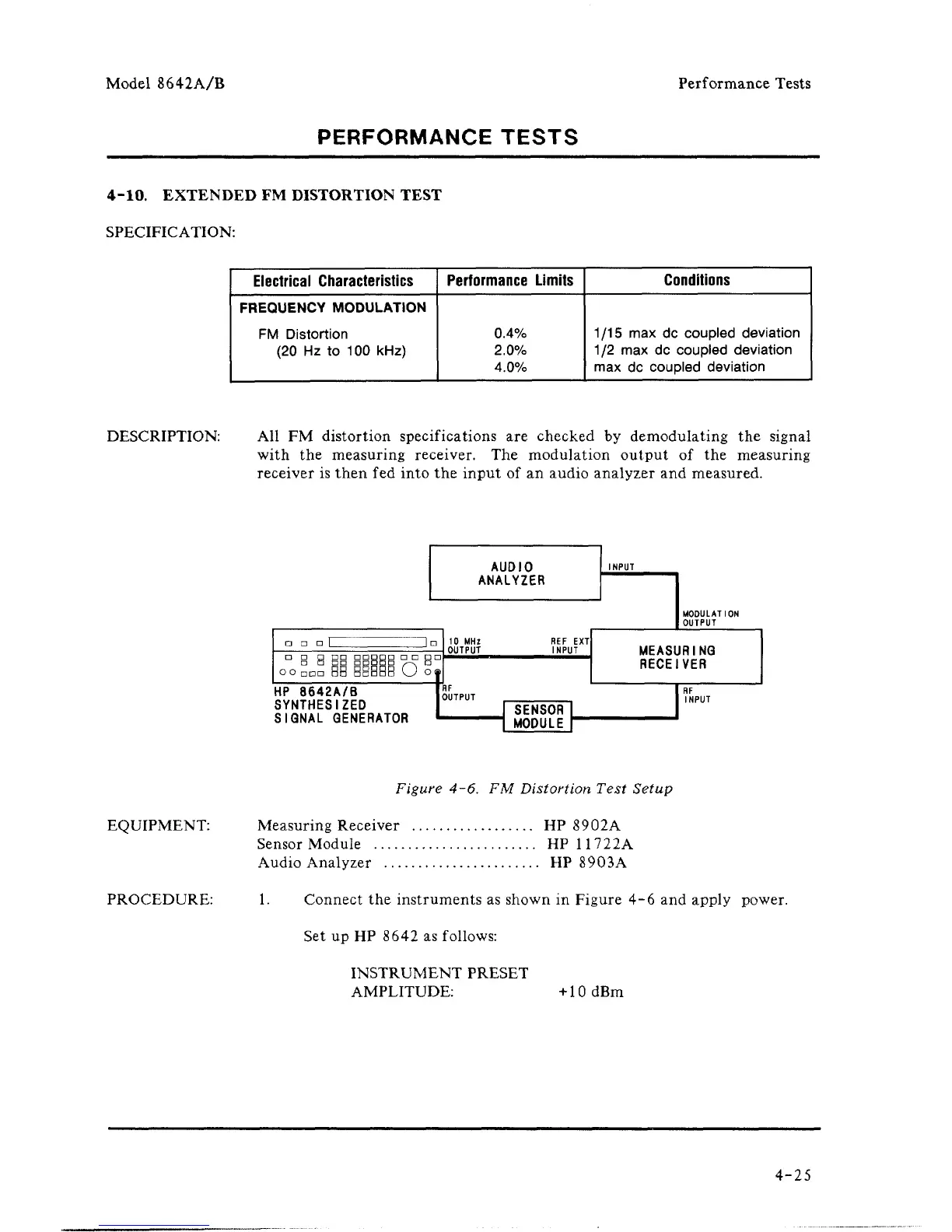
Figure 4-6. FM Distortion Test Setup
Measuring Receiver HP 8902A
Sensor Module HP 11722A
Audio Analyzer HP 8903A
1.
Connect the instruments as shown in Figure 4-6 and apply power.
Setup HP 8642 as follows:
INSTRUMENT PRESET
AMPLITUDE: +10dBm
4-25


 To Next Page