Model 8642A/B
Performance Tests
PERFORMANCE TESTS
OSCILLOSCOPE
□ DO □□ DDDDD □ n cm
n □
□ □
BnnD" ~
,-, r,
an
DDDD
OODDD
an
Bono
O
RF
OUTPUT
R
HP
8642A/B
SYNTHESIZED
SIGNAL GENERATOR
MIXER
RF
OUTPUT
1 MHz
LPF
SPECTRUM
ANALYZER
INPUT
SIGNAL
GENERATOR
OUT
LOW-NOISE
AMP
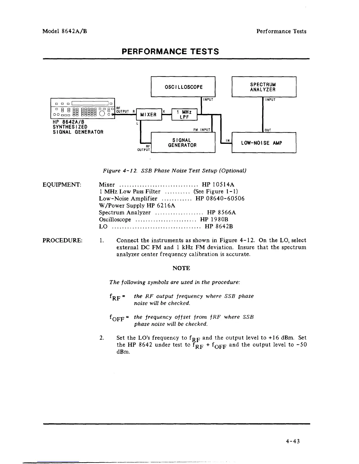
Figure 4-12. SSB Phase Noise Test Setup (Optional)
EQUIPMENT:
Mixer HP 10514A
1 MHz Low Pass Filter (See Figure 1-1)
Low-Noise Amplifier HP 08640-60506
W/Power Supply HP 6216A
Spectrum Analyzer HP 8566A
Oscilloscope HP 1980B
LO HP 8642B
PROCEDURE:
1.
Connect the instruments as shown in Figure 4-12. On the LO, select
external DC FM and 1 kHz FM deviation. Insure that the spectrum
analyzer center frequency calibration is accurate.
NOTE
The following symbols are used in the procedure:
fgp = the RF output frequency where SSB phase
noise will be checked.
'OFF
the frequency offset from fRF where SSB
phase noise will be checked.
2.
Set the LO's frequency to f^p and the output level to +16 dBm. Set
the HP 8642 under test to f^p + fQFF
anc
^
t
^
ie
out
P
ut
l
eve
l
to
"^0
dBm.
4-43


 To Next Page