EasyManua.ls Logo

HP L1710

HP L1710
78 pages
To Next Page IconTo Next Page
Loading...
17" LCD Color Monitor HP L1710
1
Service
Service
Service
Horizontal Frequency
24- 83 kHz
TABLE OF CONTENTS
Description Page Description Page
SAFETY NOTICE
ANY PERSON ATTEMPTING TO SERVICE THIS CHASSIS MUST FAMILIARIZE HIMSELF WITH THE CHASSIS
AND BE AWARE OF THE NECESSARY SAFETY PRECAUTIONS TO BE USED WHEN SERVICING ELECTRONIC
EQUIPMENT CONTAINING HIGH VOLTAGES.
CAUTION: USE A SEPARATE ISOLATION TRANSFOMER FOR THIS UNIT WHEN SERVICING
Table Of Contents.......……..............................…........1
Revision List.…........................................……......2
1. Monitor Specification..............................………........4
2. LCD Monitor Description…………………………….......5
3. Operation Instruction…………...............……...........6
3.1. General Instructions...........................…...........6
3.2. Control Button…………….…..............……...............6
3.3 Adjusting the Picture...........................…............7
4. Input/Output Specification............……………............11
4.1. Input Signal Connector............………….................11
4.2. Factory Preset Display Modes......…..................11
5. Panel Specification.....………………..................12
5.1. General Feature…….....………………..................12
5.2. Optical Characteristics………………………………14
6. Block Diagram……...................…………................17
6.1 Software Flow Chart………………………………...17
6.2.Electrical Block Diagram……………..….......19
7. Schematic……………......................................21
7.1 Main Board....……….......................................21
7.2 Power Board.….……....................................25
7.3 Key Board…………………………………………..29
8.PCB Layout..…….......................................30
8.1. Main Board………........................................30
8.2. Power Board….......................................32
8.3. Key Board………............….......................34
9. Maintainability……….......................................35
9.1. Equipments and Tools Requirement..............35
9.2. Trouble Shooting……….............................36
9.2.1 Main Board…………..............................36
9.2.2 Power Board………..............................38
9.2.3 Key Board…………..............................40
10 White-Balance, Luminance adjustment...41
11.Mechanical Instructions……………..…...….......43
12. Monitor Exploded View………………..…....….......49
13. BOM List………………………………..……………50
14. Different Parts List.........…………..........................61

Other manuals for HP L1710

Question and Answer IconNeed help?

Do you have a question about the HP L1710 and is the answer not in the manual?

HP L1710 Specifications

General IconGeneral
BrandHP
ModelL1710
CategoryMonitor
LanguageEnglish

Summary

1. Monitor Specification

2. LCD Monitor Description

Monitor Block Diagram

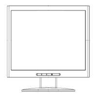
Visual representation of the monitor's main components and their interconnections.

3. Operation Instructions

3.1 General Instructions

Basic steps for setting up and powering on the monitor.

3.2 Control Button

Description and function of each control button on the monitor's front panel.

3.3 Adjust the Picture

Details on adjusting picture settings like brightness, contrast, and image control via OSD.

4. InputOutput Specification

4.1 Input Signal Connector

Pinout details for the D-SUB VGA connector.

4.2 Factory Preset Display Modes

List of supported resolutions, horizontal, and vertical frequencies.

5. Panel Specification

5.1 General Feature

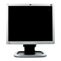
General specifications and features of the LCD panel used in the monitor.

5.2 Optical Characteristics

Detailed optical performance parameters of the LCD panel.

6. Block Diagram

6.1 Software Flow Chart

Diagram illustrating the monitor's software operation flow.

6.2 Electrical Block Diagram

Schematic showing the electrical interconnections of the monitor's main components.

7. Schematic

7.1 Main Board

Detailed electrical schematic for the monitor's main logic board.

7.2 Power Board

Electrical schematic of the monitor's power supply and inverter board.

7.3 Key Board

Schematic diagram for the monitor's button control interface.

8. PCB Layout

8.1 Main Board

Physical layout of components on the main logic board.

8.2 Power Board

Physical component layout for the power board.

8.3 Key Board

Physical layout of components on the key board.

9. Maintainability

9.1 Equipments and Tools Requirement

List of necessary tools and equipment for servicing the monitor.

9.2 Trouble Shooting

Troubleshooting guide for common monitor issues.

10. White- Balance, Luminance Adjustment

11. Mechanical Instructions

12. Monitor Exploded View

13. BOM List

14. Different Parts List

Related product manuals