4.
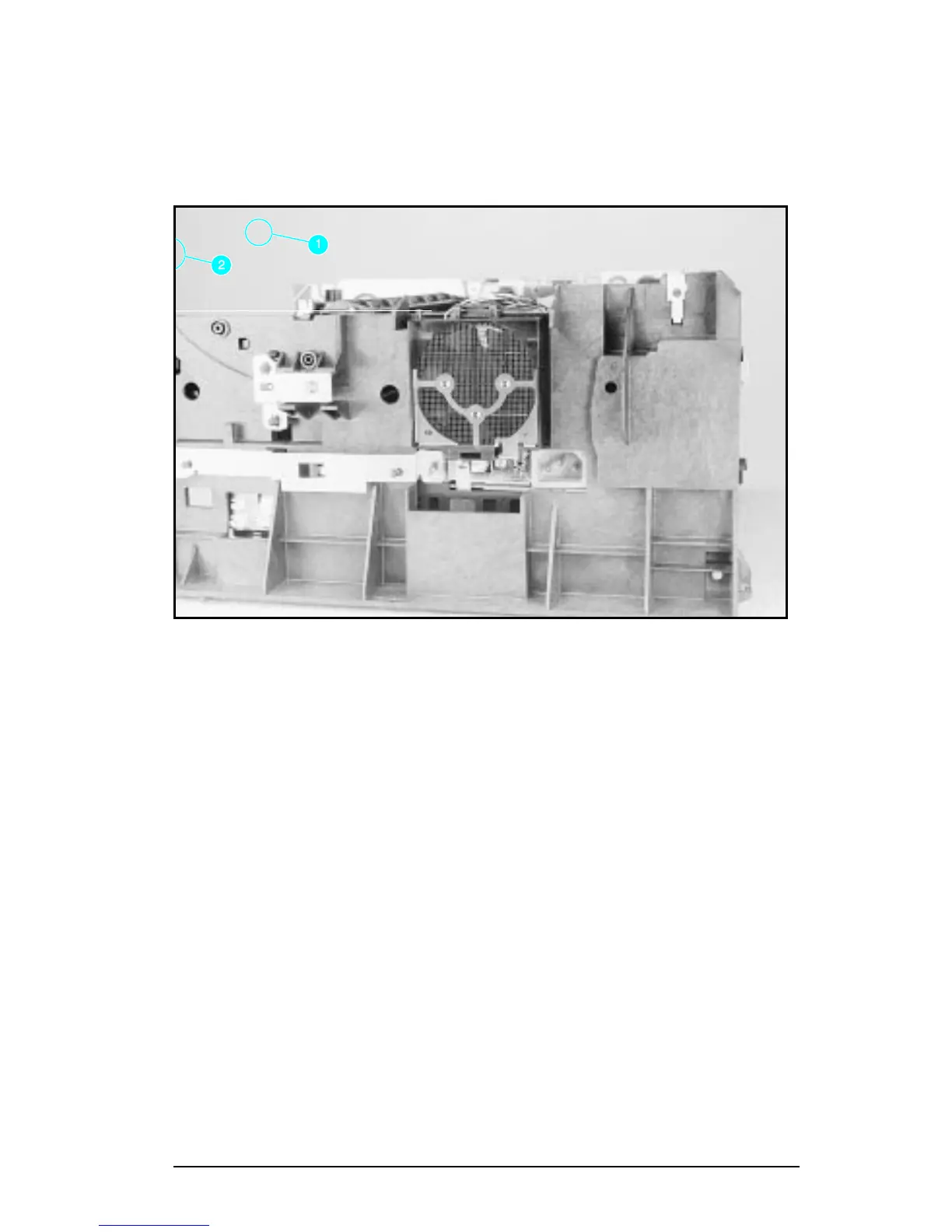
On the left side, remove the (2) screws that attach the
grounding strap to the Gear Train Assembly (see callout 1 in
Figure 6-36 of the Combined Service Manual). Turn the
assembly upside-down before proceeding with further steps.
5.
Remove the (5) self-tapping screws and the (1) machine screw
with star washer from the bottom of the DC Controller
Assembly. (See callouts
2
and
3
in Figure 6-36 in the Combined
Service Manual.)
6.
Lift the DC Controller Assembly away from the printer frame.
Figure 28 Grounding Spring screw location.
HP LaserJet 5P/5MP, 6P/6MP Printer Service Supplement
Removal and Replacement
57
 Loading...