4–40 Maintenance and Service Guide
Removal and replacement procedures
✎
Steps 5 through 8 apply only to computer models equipped with graphics subsystems having discrete memory.
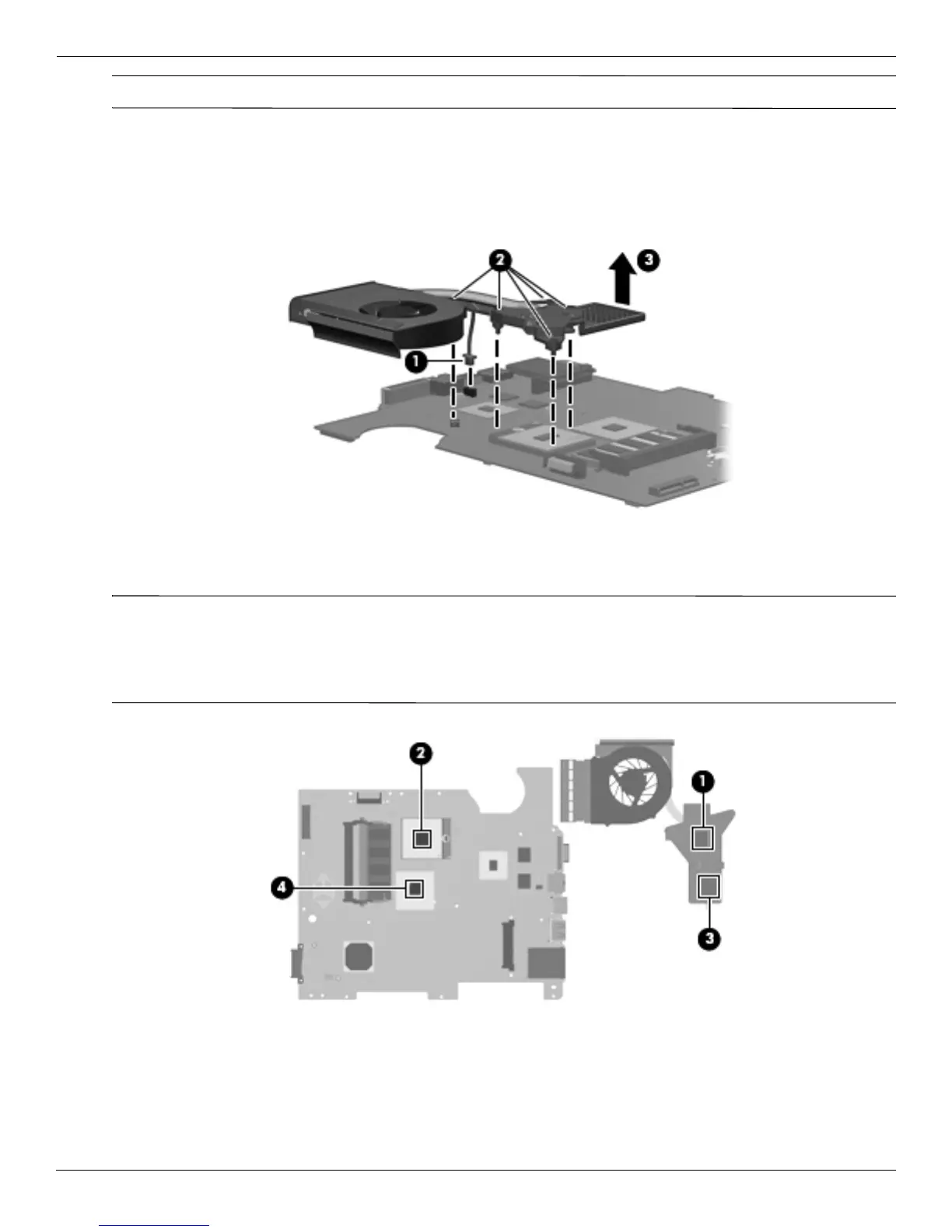
5. Turn the system board right-side up, with the front toward you.
6. Disconnect the fan cable from the system board 1.
7. Loosen the 5 Phillips PM2.5×6.0 spring-loaded captive screws 2 that secure the fan/heat sink assembly.
8. Remove the fan/heat sink assembly 3 by lifting it straight up.
The following illustration shows the replacement thermal material locations for computer models graphics
subsystems having UMA memory
✎
The thermal material must be thoroughly cleaned from the surfaces of the fan/heat sink assembly and the system
board components each time the fan/heat sink assembly is removed. Thermal grease is located on the section of
the fan/heat sink assembly 1 that services the processor 2. A thermal pad is located on the section of the
fan/heat sink assembly 3 that services the Northbridge chip 4. Replacement thermal grease and pads are
included in spare parts kits for all system boards, fan/heat sink assemblies, and processors.
 Loading...