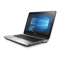
3. Loosen the two PM2.0×5.0 captive screws (2) from the system board, and then remove the fan
(3).
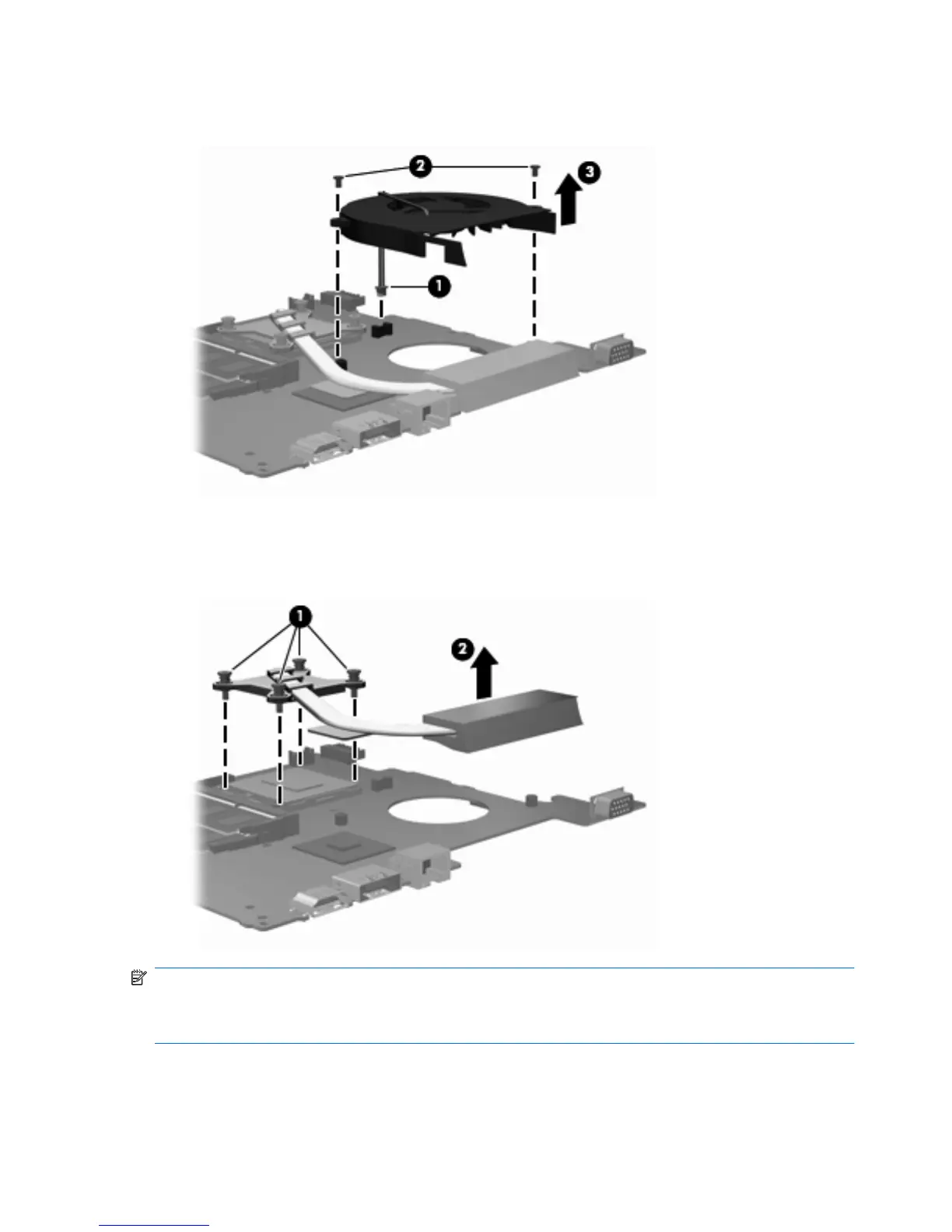
4. Following the sequence stamped into the heat sink, loosen the four PM2.5×10.0 captive screws
(1) that secure the heat sink to the processor.
5. Lift the heat sink off the processor (2).
NOTE: The thermal material must be thoroughly cleaned from the surfaces of the heat sink
components (1) and (2), and the system board components (3) and (4), each time the heat sink is
removed. Replacement thermal material is included with all heat sink and system board spare part
kits.
76 Chapter 4 Removal and replacement procedures