Removal and replacement procedures 37
9.
Remove the drive cage assembly.
To replace the component, reverse the removal procedure.
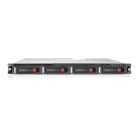
SFF drive cage assembly
The drive cage assembly includes the front panel LEDs and buttons (on page 72), drive cage backplane, and
cables.
IMPORTANT: The embedded Smart Array B120i controller supports a maximum of four SATA
drives.
To remove the component:
1. Power down the server (on page 27).
2. Remove all power:
a. Disconnect each power cord from the power source.
b. Disconnect each power cord from the server.
3. Remove the server from the rack (on page 28).
4. If the server is installed in a friction rail system, remove the friction rails from the chassis. For more
information, see the documentation that ships with the rail system.
5. Remove the access panel ("Access panel" on page 29).
6. Remove the processor air baffle ("Processor air baffle" on page 30).
7. Remove all hot-plug drives ("Hot-plug drive" on page 34).
 Loading...