Removal and Replacement Procedures 33
Table 4 Cable Connections
Cable To System Board Designator
SATA 1 Connector System board P17
SATA 5 Connector System board P12
Power Supply Management Interface
Connector
System board J55
External HDD LED Connector System board P23
Front USB 2.0 Cable Header System board P20
5-pin System Fan 4 Header System board P21
Internal USB 2.0 Header for Tape
Drive
System board J36
Internal USB 2.0 Port System board J32
PATA ODD System board P25
5-pin System Fan 3 Connector System board P22
8-pin Power Connector System board P24
5-pin System Fan 1 Connector System board P8
24-pin Power Connector System board P7
4-pin Power Connector System board P6
5-pin System Fan 2 Header (with
extension cable)
System board P4
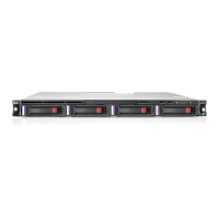
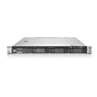
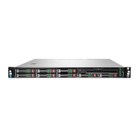
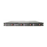
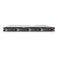
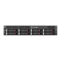
Drive Bay Configuration
The server supports a maximum of nine drive bays – eight bays for 1-inch hard disk drives and one
drive bay for an optical media drive.
 Loading...