Prerequisites
The 12G SAS Expander Card supports up to 24 SFF drives, depending on which options are also installed in
the server.
The following components must be installed:
• Storage controller
• Drive cages
◦ 24SFF drive configuration—Bay 1, bay 2, and bay 3 installed with 8SFF front drive cages
◦ 18SFF drive configuration—Bay 1 Universal Media Bay installed with 2SFF drive cage option, and bay
2 and bay 3 installed with 8SFF front drive cages.
◦ 16SFF drive configuration—Bay 2 and bay 3 installed with 8SFF drive cages
Procedure
1. Power down the server (Power down the server on page 38).
2. Remove all power:
a. Disconnect each power cord from the power source.
b. Disconnect each power cord from the server.
3. Do one of the following:
• Extend the server from the rack (Extend the server from the rack on page 38).
• Remove the server from the rack (Removing the server from the rack on page 39).
4. Remove the access panel (Removing the access panel on page 40).
5. If installed, do the following:
a. Remove the air baffle (Removing the air baffle on page 42).
b. Remove the processor mezzanine tray (Removing the processor mezzanine tray on page 47).
c. Remove the joint board (Removing the 2P pass-through performance board on page 48).
d. Remove the 2P pass-through performance board (Removing the 2P pass-through performance
board on page 48).
6. Remove the fan cage (Removing the fan cage on page 46).
7. Remove the primary PCIe riser cage (Removing the PCIe riser cages on page 44).
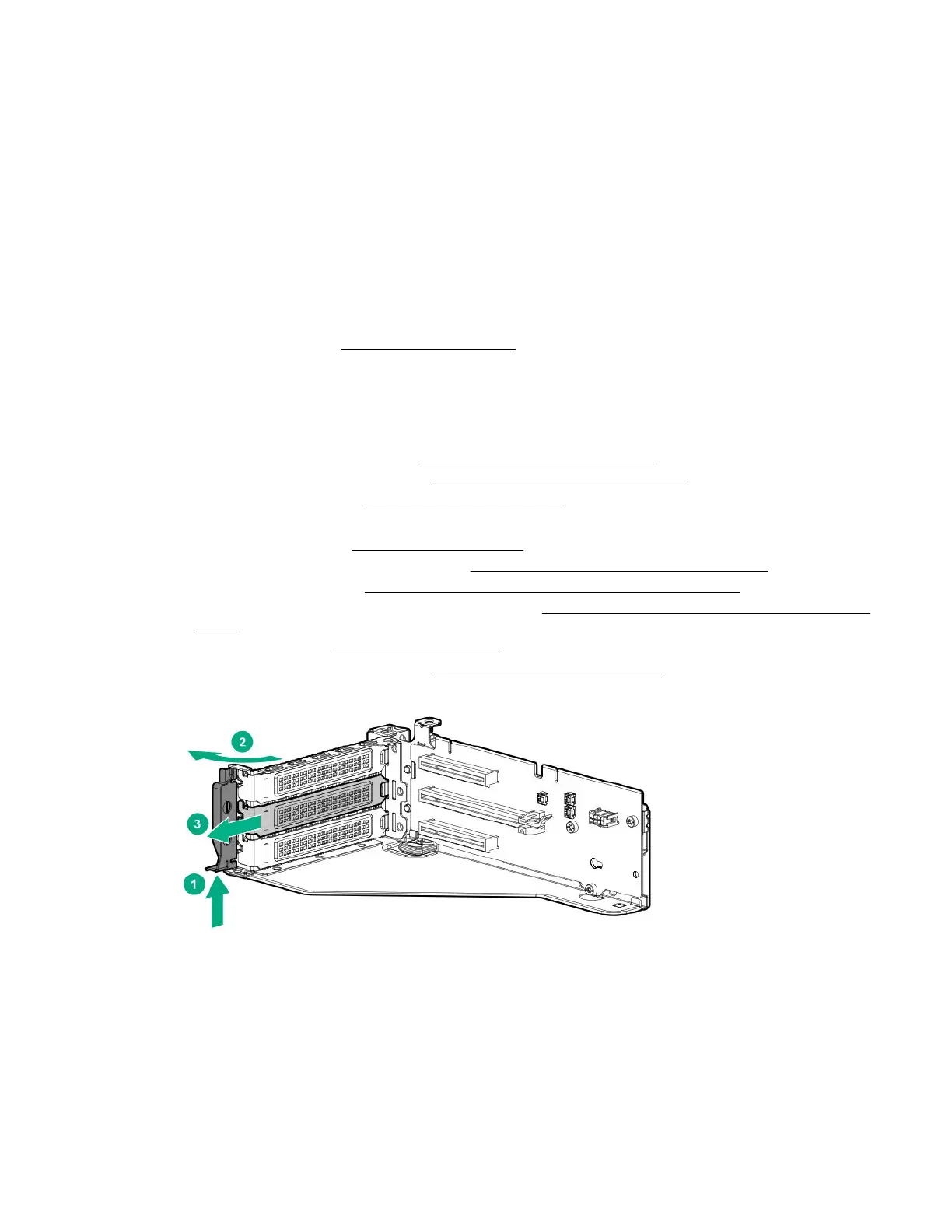
8. Remove the expansion slot blank from slot 2.
9. Using the labels on the cables to determine the correct connections, connect the cables to the SAS
expander card.
a. Depending on the ports on the controller, connect the appropriate controller cables to the SAS
expander card.
b. Depending on the drive configuration, connect the appropriate drive cage cables to the SAS expander
card.
Installing hardware options 97
 Loading...