Item Code Component
26 Full-height
half-length Slot 1
PCIe x4 (1)
Full-height/half-length PCIe Gen1 x4 slot (x1)
27 BATSOCKET1 System battery
28 REARFAN1 System fan cable connector
Opening the server
Access panel removal
Front bezel removal
Installing a memory module
The system has four DIMM slots that support up to 8 GB maximum
system memory (2 GB in each of the four DIMM slots).
Observe the following important guidelines when installing memory
modules:
• Use only HP supported PC3-10600 unbuffered DIMM in 1 GB,
2 GB, or 4 GB capacities.
• Supported DIMM configurations include:
o Single DIMM (non-interleaving) – It must be installed in the
DIMM2A slot.
o Two DIMMs (interleaving) – For optimum memory
performance, install in the DIMM2A and DIMM4B slots.
NOTE: To allow an interleaving memory
configuration, the Memory Interleaving field in the
Advanced | Advanced Chipset Control menu of the
BIOS Setup must be set to
Enabled.
o Four DIMMs
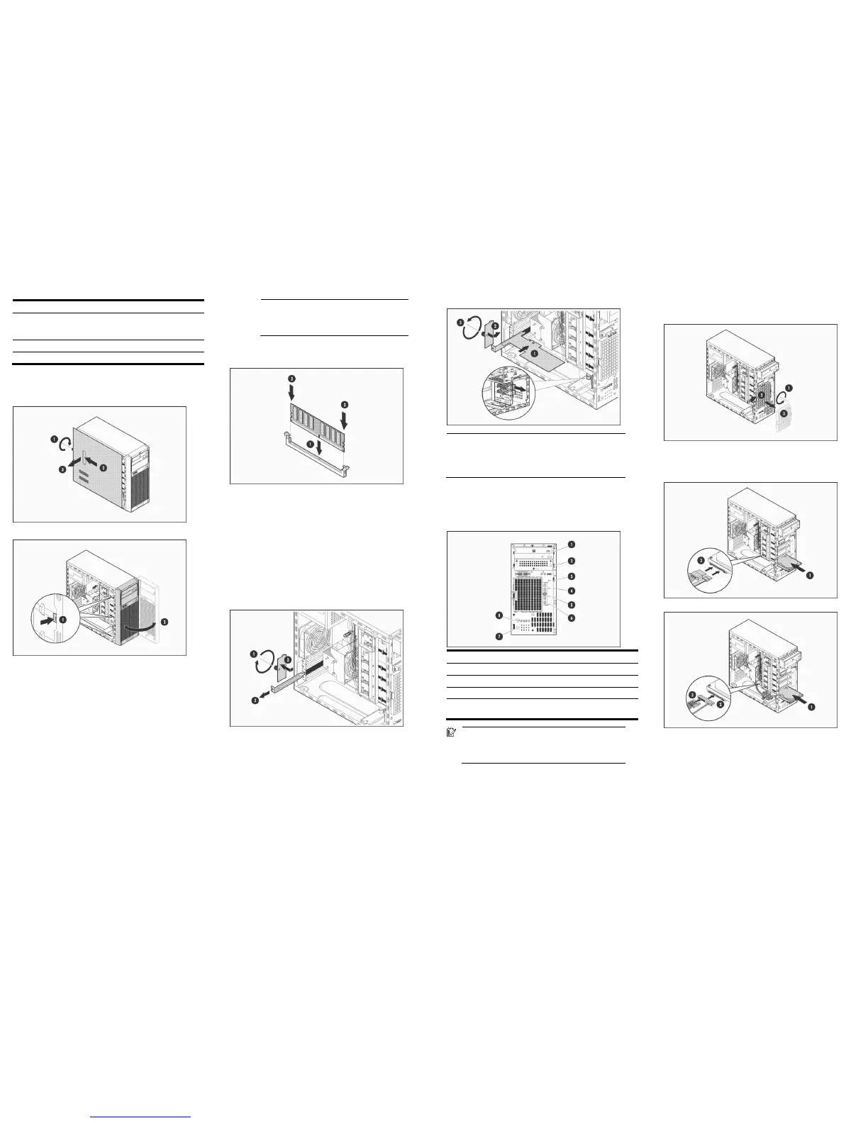
Memory module installation
Installing an expansion board
The server has four expansion slots. From top to bottom these are:
• 22 – Full-height/full-length PCIe Gen2 x16 slot (x16)
• 23 – Full-height/full-length PCIe Gen1 x8 slot (x4)
• 24 – Full-height/full-length 32-bit/33 MHz PCI slot
• 26 – Full-height/half-length PCIe Gen1 x4 slot (x1)
* The numbers indicated above correspond to the “System board
components” figure label.
Expansion board installation
1. Remove the slot cover retainer and the slot cover opposite the
expansion slot compatible with your expansion board.
2. Install the expansion board.
NOTE: For a full-length expansion board installation: Remove
first the full-length card retainer (see the zoomed in section in
the figure above) opposite the expansion slot you are using
and secure the board in it, and then install the board in the
slot.
Installing a hard drive
The two upper drive bays are primarily for removable media drives,
while the four lower drive bays are only for hard drives (3.5-inch
non-hot-plug SAS or SATA drives).
Item Component Item Component
1 1
st
removable media drive 5 2
nd
SAS/SATA hard drive
2 2
nd
removable media drive 6 1
st
SAS/SATA hard drive
3 4
th
SAS/SATA hard drive 7 HDD spare screws
4 3
rd
SAS/SATA hard drive 8 Removable media drive spare
screws
IMPORTANT: Install a SAS controller board first before
configuring a SAS hard drives. It is recommended that
this controller board be installed in the full-height/
full-length PCIe Gen2 x16 expansion slot.
Hard drive installation
1. Remove the HDD EMI shield.
2. Remove four spare HDD screws from the front chassis, and then
insert them into the new drive.
3. Install the new hard drive.
SATA HDD
SAS HDD
Legal notices
© Copyright 2010 Hewlett-Packard Development Company, L.P.
The information contained herein is subject to change without notice. The
only warranties for HP products and services are set forth in the express
warranty statements accompanying such products and services. Nothing
herein should be construed as constituting an additional warranty. HP shall
not be liable for technical or editorial errors or omissions contained herein.
 Loading...