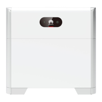
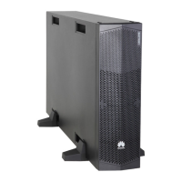
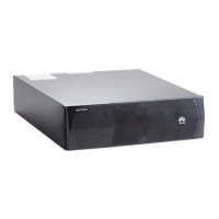
Figure 7-8 Positions of the DC circuit breakers of battery racks in the battery cabin
(1) Positions of the DC circuit breakers of battery racks in the battery cabin
Step 2 (Optional) Switch on UPS circuit breaker 5FCB (corresponding to number 8 in the
gure of switches).
● The UPS switch position is reserved only in some models. If the UPS switch is needed,
install it by yourself.
● Perform this operation only in microgrid or o-grid scenarios.
Step 3 Switch on circuit breaker 2FCB1 on the SPD (corresponding to number 5 in the
gure of switches) and check that the SPD display window is green.
Step 4 Switch on the circuit breaker 1QA for the AC input power cable of the ESS.
(corresponding to number 6 in the
gure of switches)
● After turning on the main switch, immediately check that the L1, L2, and L3
phase voltages are 220 V AC/230 V AC.
● If the phase voltage displayed on the digital display meter is 400 V or other
values, the cables between the L1, L2, L3, and N wires may be incorrectly
connected. In this case, check the cables. Do not power on devices before
checking cables. Otherwise, devices such as air conditioners may be damaged.
Step 5 Switch on all circuit breakers of the ESS power distribution system.
LUNA2000-2.0MWH Series Smart String ESS
User Manual 7 Powering On the System
Issue 08 (2022-11-15) Copyright © Huawei Technologies Co., Ltd. 151

 Loading...


