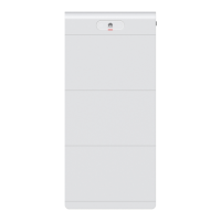
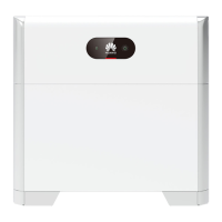
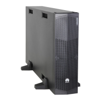
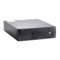
Figure 7-9 Position of the power switch in the extinguishant control panel
(1) Position of the right power switch in the
extinguishant control panel
(2) Position of the left power switch in the
extinguishant control panel
5. Switch on the PSU AC input circuit breaker 6FCB1.
If a 3 U subrack is congured, the PSU switch is in the subrack. If a 2 U subrack is
congured, the PSU switch is in (2) in the gure that shows switch positions.
6. On the subrack, switch on the DC input circuit breakers 7FCB1 and (optional)
7FCB2, the exhaust fan controller circuit breakers 7FCB4 and 7FCB5, and the
air conditioner circuit breaker 7FCB6 of the control unit cabin in sequence.
(corresponding to number 3 in the
gure of switches)
7. Switch on the circuit breakers of the battery pack fan in sequence.
(corresponding to number 4 in the gure of switches)
8. Switch on the circuit breakers of the Smart Rack Controller. (corresponding to
number 4 in the
gure of switches)
Step 6 Switch on the DC circuit breakers in the control unit cabin. (corresponding to
number 7 in the gure of switches)
Table 7-2 Switch conguration
Models
Air Conditioner
Position in the Battery
Cabin
DC Circuit Breakers No. in
the Control Unit Cabin
LUNA2000-2.0MWH-1
HX
1/2/4/5/7/8/10/11 1Q2–6Q2
LUNA2000-2.0MWH-1
HX
1/3/5/7/9/11 1Q2–6Q2
LUNA2000-2.0MWH-2
HX
1/3/5/7/9/11 1Q2–3Q2
LUNA2000-2.0MWH-2
HX
2/4/6/8/10/12 1Q2–3Q2
LUNA2000-2.0MWH Series Smart String ESS
User Manual 7 Powering On the System
Issue 08 (2022-11-15) Copyright © Huawei Technologies Co., Ltd. 153

 Loading...


