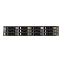
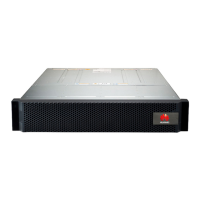
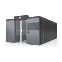
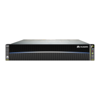
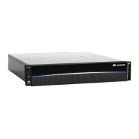
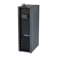
Figure 4-2 Power-on process of the o-grid PV+ESS system
Table 4-2 Power-on process description of the o-grid PV+ESS system
Step
Task Power-On Operation
1 Starting the UPS For details, see the documents provided by the
vendor.
2 - Turn on the UPS power switch on the power
distribution equipment side.
Powering on the
UPS-ESS auxiliary
power supply (for
black start)
1. Turn on the ESS power switch on the UPS
side.
2. Turn on the UPS cable inlet switch 5FCB in
the ESS.
Powering on the
auxiliary power
supply of the
UPS-SACU or
SmartLogger
1. Turn on the SACU or SmartLogger power
switch on the UPS side.
2. Turn on the switch on the SACU or
SmartLogger side:
● If the SACU is congured:
SmartACU2000D-D-00: Turn on the
SACU input switch QF03 and the three-
phase input switch FU01 in the SACU.
SmartACU2000D-D-06: Turn on the
SACU input switch QF03.
● If the SmartLogger3000A is congured,
turn on the power switch (if any)
between the SmartLogger3000A and the
UPS based on site requirements.
Commercial and Industrial Microgrid Energy Storage
Solution
Quick Guide (With Third-Party Microgrid Central
Controller) 4 System Power-On and Commissioning
Issue 04 (2023-12-18) Copyright © Huawei Digital Power Technologies Co., Ltd. 23

 Loading...
