Networking Requirements
SwitchA, SwitchB, SwitchC, and SwitchD run MSTP. In this example, MSTP runs on Layer 2
interfaces of the Switches.
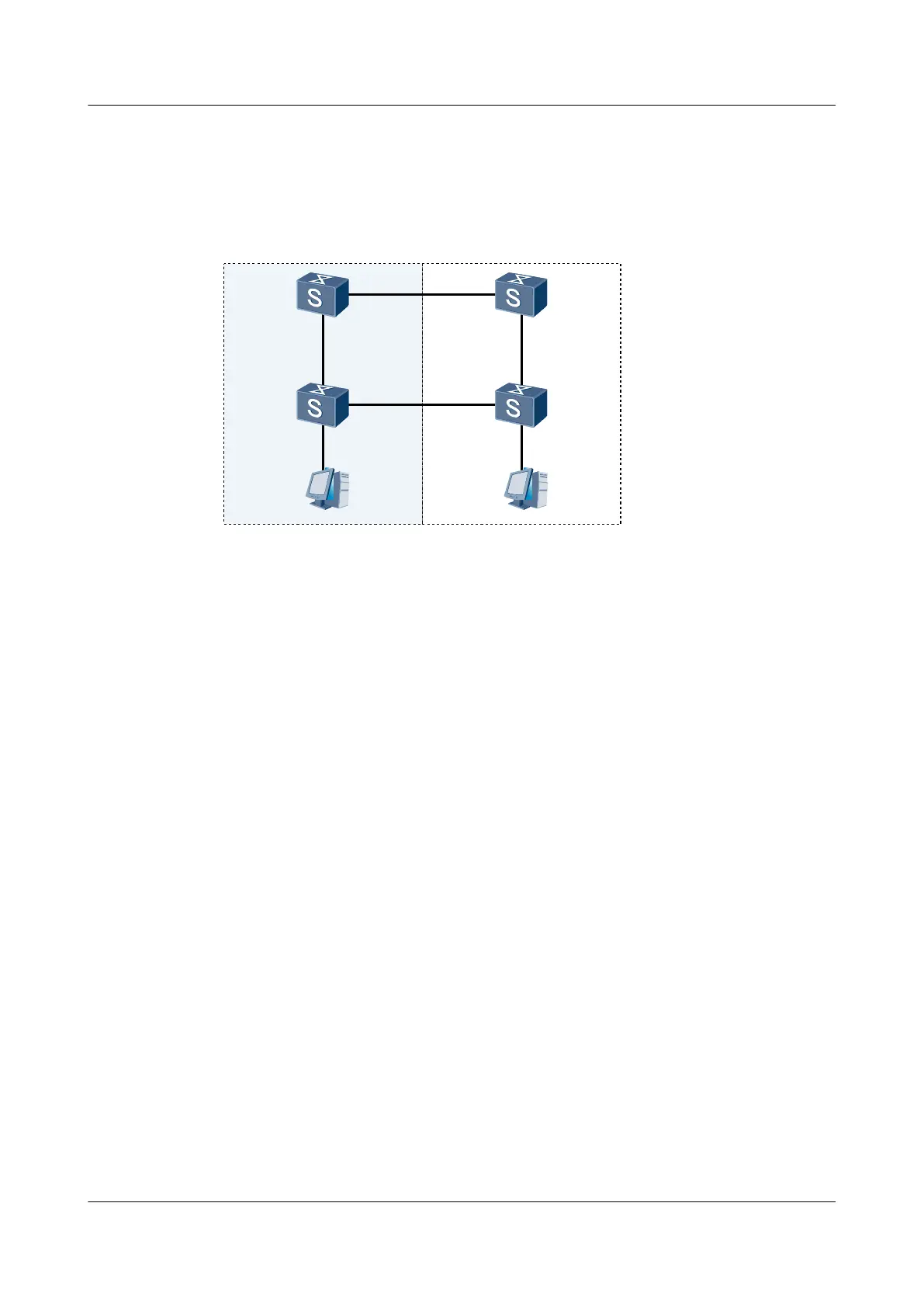
Figure 9-9 Networking diagram of basic MSTP configurations
SwitchA SwitchB
SwitchDSwitchC
GE1/0/1
GE1/0/2 GE1/0/2
GE1/0/1
GE2/0/1
GE1/0/1
GE1/0/2 GE1/0/2
GE1/0/1
GE2/0/1
Configuration Roadmap
The configuration roadmap is as follows:
1. Add SwitchA and SwitchC to MST region RG1, and create MSTI1.
2. Add SwitchB and SwitchD to MST region RG2, and create MSTI1.
3. Configure SwitchA as the CIST root.
4. In RG1, configure SwitchA as the CIST regional root and regional root of MSTI1.
Configure the root protection function on GE 1/0/2 and the GE 1/0/1 on SwitchA.
5. In RG2, configure SwitchB as the CIST regional root and SwitchD as the regional root of
MSTI1.
6. On SwitchC and SwitchD, connect GE 1/0/1 to a PC and configure GE 1/0/1 as an edge
port. Enable BPDU protection on SwitchC and SwitchD.
7. Configure the Switches to calculate the path cost by using the algorithm of Huawei.
Data Preparation
To complete the configuration, you need the following data:
l Region that SwitchA and SwitchC belong to: RG1
l Region that SwitchB and SwitchD belong to: RG2
l Numbers of the GE interfaces, as shown in Figure 9-9
l VLAN IDs: 1-20
Procedure
Step 1 Configure SwitchA.
Quidway S7700 Smart Routing Switch
Configuration Guide - Ethernet 9 MSTP Configuration
Issue 01 (2011-07-15) Huawei Proprietary and Confidential
Copyright © Huawei Technologies Co., Ltd.
459

 Loading...


