Procedure Operation Nixie Tube Display
4 Press the left button to switch
between the high-, middle-, and
low-order nixie tubes. Press the
right button to adjust the value.
Adjusted group number
(middle- or low-order
nixie tube blinking)
5 Hold down the left or right button
to save the settings.
Group number (static).
Then, the voltage
display screen is
displayed.
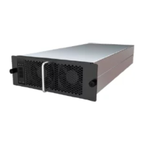
2.5 Module Ports
Figure 2-4 DC output and signal ports
Table 2-10 Output port denition
Pin
Item Function
1, 2 1000 V DC– Negative output (pins 1 and 2
must be connected in parallel)
3, 4 1000 V DC+ Positive output (pins 3 and 4
must be connected in parallel)
5 CANBH CAN high-level signal
6 CANBL CAN low-level signal
7 CANBH CAN high-level signal
8 CANBL CAN low-level signal
9 CAN_GND Signal ground
10 LINK_CHECK_OK Insertion and removal control
11 URGENT_TURN_OFF+ Emergency shutdown+
R100030G1 Charging Module
User Manual 2 Product Description
Issue 05 (2021-11-16) Copyright © Huawei Digital Power Technologies Co., Ltd. 16
 Loading...