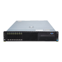
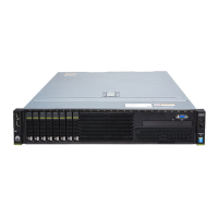
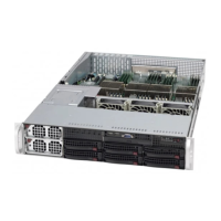
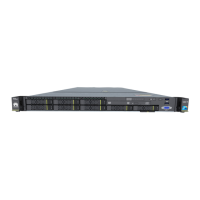
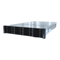
1 Fault diagnosis LED 2 Health status indicator
3 UID button/indicator 4 Power button/indicator
5 Right mounting ear 6 Label plate with an ESN label
7 Drives (numbered 0 to 11
from top to bottom and from
left to right)
8 Drive fault indicator
9 Drive activity indicator 10 USB 2.0 port
11 Left mounting ear 12 Network port link status indicators
(numbered 1 to 4 from top to
bottom)
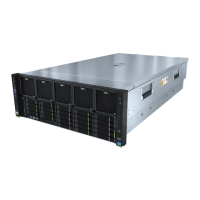
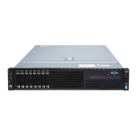
Figure 2-5 shows the front panel of an RH2288H V3 with twelve 3.5-inch drives,
including four NVMe PCIe SSDs.
Figure 2-5 Front panel of an RH2288H V3 with twelve 3.5-inch drives, including
four NVMe PCIe SSDs
1
Fault diagnosis LED 2 Health status indicator
3 UID button/indicator 4 Power button/indicator
5 Right mounting ear 6 NVMe PCIe SSD yellow indicator
7 NVMe PCIe SSD green
indicator
8 Label plate with an ESN label
9 NVMe PCIe SSDs (numbered
8 to 11 from left to right and
from top to bottom)
10 Drives (numbered 0 to 7 from top
to bottom and from left to right)
11 Drive fault indicator 12 Drive activity indicator
13 USB 2.0 port 14 Left mounting ear
15 Network port link status
indicators (numbered 1 to 4
from top to bottom)
- -
RH2288H V3 Server
User Guide 2 Overview
Issue 46 (2022-12-28) Copyright © Huawei Technologies Co., Ltd. 10
 Loading...
