You have powered o the RH8100 V3. For details, see 6.2 Powering O the
RH8100 V3. Then you have removed all power cables from the server.
Data
● You have obtained the cabinet number and chassis number of the RH8100 V3.
● You have located the RH8100 V3 based on the preceding information, and
labeled its panel to prevent misoperations.
● You have determined the position on the RH8100 V3 for removing the front
I/O module.
Tools
● ESD gloves
● Packaging materials, for example, an ESD bag
Procedure
Step 1 Wear an ESD wrist strap or ESD gloves. For details, see 1 Safety Instructions.
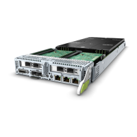
Step 2 Raise both ejector levers on the front I/O module. See step (1) in Figure 5-93.
Step 3 Pull the front I/O module out of the slot while holding the ejector levers. See step
(2) in Figure 5-93.
Figure 5-93 Removing a front I/O module
Step 4 Remove the RAID controller cards, supercapacitor, and hard disk backplane from
the front I/O module, and place the front I/O module in an ESD bag.
For details, see 5.7.5 Removing a RAID Controller Card, 5.7.7 Removing a
Supercapacitor, and 5.7.9 Removing a Hard Disk Backplane.
----End
RH8100 V3 Server
User Guide 5 Removing and Installing Parts of the RH8100 V3
Issue 30 (2019-12-19) Copyright © Huawei Technologies Co., Ltd. 209

 Loading...