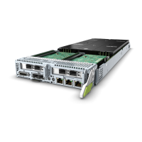
Figure 2-18 Mapping between logical CPU sockets and physical CPU sockets
(single-system mode)
Table 2-21 and Table 2-22 describe the mapping between logical CPU sockets
and physical CPU sockets on the RH8100 V3 in dual-system mode. Figure 2-19
shows the mapping between logical CPU sockets and physical CPU sockets.
Table 2-21 Mapping between logical CPU sockets and physical CPU sockets in
system A
N-core CPU
System A
Logical CPU Core Logical CPU
Socket
Ph
ysi
cal
CP
U
So
ck
et
0 to N-1 4N to 5N-1 0 1
N to 2N-1 5N to 6N-1 1 3
2N to 3N-1 6N to 7N-1 2 4
3N to 4N-1 7N to 8N-1 3 2
RH8100 V3 Server
User Guide 2 About the RH8100 V3
Issue 30 (2019-12-19) Copyright © Huawei Technologies Co., Ltd. 47
 Loading...
