®
Wiring Device-Kellems
Hubbell Incorporated (Delaware)
Shelton, CT 06484
(800) 288-6000
www.hubbell-wiring.com
Hubbell Load Control Solutions
WS Series Dual Circuit Passive Infrared Occupancy / Vacancy Wall Switch Sensors
Installation and Operating Instructions
PD2733 Page 1 03/16
Top View / Vue en plan / Vista por encima
Side View / Vue de côté / Vista lateral
Minor Motion / Mouvement occasionnel / Movimiento ocasional
Major Motion / Mouvement fréquent / Movimiento frecuente
Floor/Plancher/Piso
0' [m]
20' [6,1 m]
20' [6,1 m]
40' [12,2 m]
40' [12,2 m]
16' [4,9 m]
12' [3,7 m]
SPECIFICATIONS (WS1020, WS1021, WS1024, WS1025,
WS1020N, WS1021N, WS1024N, WS1025N models)
• 1200 sq. ft coverage area
• Electrical Ratings :
120VAC – 600 W Incandescent, 5A Ballast, CFL/LED, 1/6 HP
• Adjustable Time Delay: 30 seconds to 20 minutes
• Zero-Cross Switching Circuitry
• UL Listed
• Both Neutral and Ground wire versions available
• Auto/ON and Manual ON (Vacancy) Modes Available
PRECAUTIONS
CAUTION: RISK OF ELECTRICAL SHOCK. Turn power OFF at
service panel before beginning installation. Never wire energized
electrical components.
CAUTION: USE COPPER CONDUCTOR ONLY.
NOTICE: For indoor use only.
NOTICE: For installation by a licensed electrician in accordance with
National and/or local Electrical Codes and the following instructions.
NOTICE: Conrm that device ratings are suitable for application prior
to installation. Do not install if any damage to product is noticed.
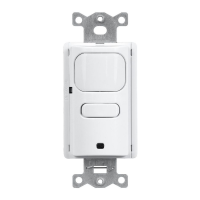
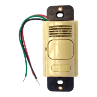
INSTALLATION
1. Turn power OFF at the service panel.
2. (For new installation) Select a suitable location for the sensor.
Make sure the sensor will not be blocked by doors or other
obstacles. In addition, make sure the sensor will not detect motion
in adjacent areas or hallways causing the lights to turn ON when
not desired. The sensor should have a line of sight view of the
occupant’s hands for best performance. Note the area of coverage
diagram. Mount the sensor 42” to 54” (107-137 cm) from the oor.
(For existing switch installation, remove old switch and replace
with sensor.)
3. Wire the sensor(s) as shown in the wiring diagrams.
Connect BLACK and BLUE wire to HOT or LINE conductor.
Connect WHITE wire to NEUTRAL conductor. (Neutral models only)
Connect RED and BROWN wire to lighting LOAD conductors.
Connect GREEN wire to equipment grounding conductor, “GND”.
(Green, Green/Yellow or Bare wire) Ground wire power sensors
must be securely connected to ground to operate.
4. Install sensor in wall box using mounting screws provided.
5. Restore power to the sensor and allow it to initialize (up to 45 sec).
6. If it is desired to change settings, remove the sensor’s front button
cover and see time delay and daylight control settings.
7. Install wall plate.
Operation
Front press switch operation: (Vacancy Version = Manual ON,
Occupancy Version = Automatic ON) Vacancy: the front press switch
must be pressed to turn the lighting ON. When the switch is pressed
to turn the lighting OFF, the lights will remain OFF until the switch
is pressed again. Occupancy: the lighting will turn ON automatically
when motion is sensed. When the switch is pressed to turn the lighting
Controls / Commandes / Mandos
English