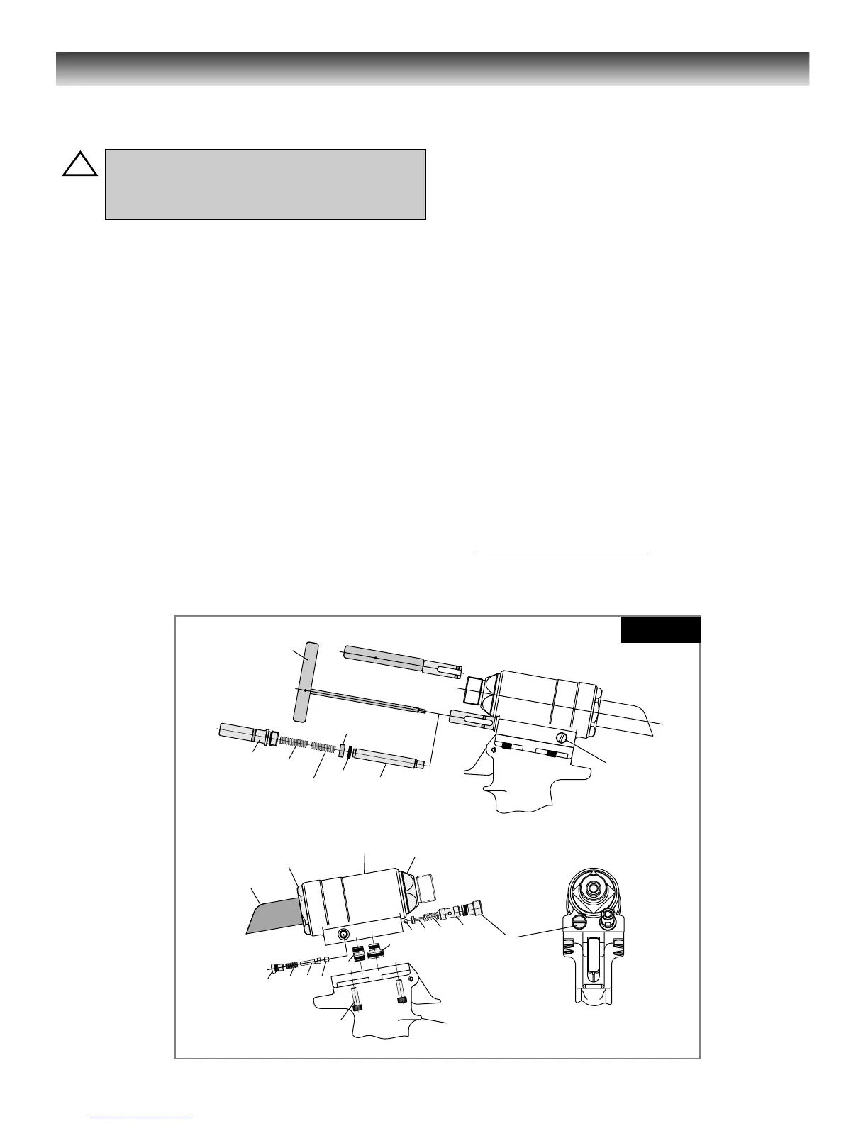
FIG. 1
Model 244/244OS Disassembly/Assembly
For component identification and Parts list refer to
Figures ( 9 & 10 ).
DISASSEMBLY
(Refer to Figures 1-3 and 9 & 10)
NOTE:
The following procedure is for complete disassembly of
tool. Disassemble only components necessary to
replace damaged O-rings, Quad-Rings, Back-up Rings,
and worn or damaged components. Always use soft jaw
vice to avoid damage to tool.
1. Disconnect air hose from tool.
2. Remove nose assembly. Follow instructions on Nose
Assembly Data sheet.
3. Insert Fill Tool, P/N 112465 through reservoir housing
and screw into Reservoir Plunger (73) locking it in the
out position (Fig1).
4. Unscrew Cap Screws (69) with 5/32 hex key. Carefully
lift Head straight up from Handle (1), remove Pull
Gland Assembly (29) and Return Gland Assembly (25)
from separated head and handle assemblies (Fig1).
5. Unscrew Plug (85) of return Pressure Relief Valve from
front of head. Remove Spring (84), valve Guide (82),
Sleeve (83) and Steel Ball (81). A small magnet is
helpful (Fig1).
6. Unscrew Bleed Plug (40). Hold over waste oil
container and release fill tool slowly (Fig1).
7. Unscrew Housing/Spacer Assembly (70) from head.
Remove two Springs (2x 71 for the 244 tool or 71 & 93
for the 244OS tool). Slide Reservoir Plunger (73) from
head. Remove spacer and Quad-Ring (72), a pick
may be used to remove the Quad-Ring (Fig1).
8. Unscrew Plug (78) of reservoir check valve from side
of head. Remove Spring (77), Check Valve Guide (76)
and Stainless Steel Ball (75) (Fig1).
9. 244 Model Only (Fig. 1 & 9)
Pintail Deflector (22) can be pulled off deflector tube at
rear of Piston.
WARNING: Be sure air hose is disconnected
from tool before cleaning, or performing
maintenance. Severe personal injury may
occur if air hose is not disconnected.
 Loading...


