Do you have a question about the Humanetics Hybrid III 5th Female and is the answer not in the manual?
| Category | Crash Test Dummy |
|---|---|
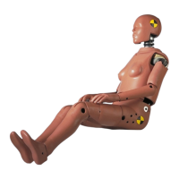
| Description | Hybrid III 5th Female crash test dummy |
| Application | Automotive safety testing |
| Material | Polyurethane foam, metal |
| Head Mass | 3.6 kg |
Provides background on the development of the Hybrid III 5th Female dummy.
Describes the manual's structure, including appendices and SAE documents.
Details the physical components and materials used in the dummy's construction.
Specifies the required clothing and footwear for testing the dummy.
Lists available instrumentation, part numbers, and channels for the dummy.
Lists specialized tools required for assembly, disassembly, and calibration.
Procedure for detaching the head-neck assembly from the torso and separating head from neck.
Steps for reattaching the neck to the head and the neck to the sternum bib.
Guidelines for checking the neck for tears or breaks before and after assembly.
Instructions for disassembling components from the head assembly.
Steps for reattaching the head skin and load cell or structural replacement.
Procedures for inspecting the head skin and skull for damage or wear.
Procedure for disassembling the neck assembly, including the neck cable.
Steps for reassembling the neck cable, nodding joint, and neck shield.
Guidelines for checking the neck for tears, nodding blocks, and axial integrity.
Procedures for detaching arm assemblies, shoulder, ribs, and other torso components.
Steps for reassembling the upper torso, including ribs, shoulders, and arms.
Using a chest depth gauge to inspect the ribs for deformation.
Procedure for separating the thorax from the lower torso and disassembling the deflection transducer.
Steps for reassembling the chest deflection transducer and related components.
Checking for proper clearance of the transducer arm to prevent contact with the spine weldment.
Exploded view and parts list for the shoulder assembly.
Procedure for disassembling the clavicle, shoulder yoke, and steel stop.
Steps for reassembling the shoulder components, including yoke and clavicle.
Checking the shoulder casting for cracks and the stop assembly for damage.
Procedure for removing the lumbar-thorax adapter, spine, and pelvic adapter.
Steps for installing the lumbar spine and associated components.
Procedure for removing the femurs and inspecting pelvis components.
Steps for reassembling the lumbar spine and inserting the femurs.
Checking the lumbar spine rubber and pelvis vinyl for tears or damage.
Procedure for detaching the upper arm from the lower arm, and removing the hand.
Steps for reattaching the wrist rotation assembly, hand, and arm components.
Checking the arm flesh for rips or tears and inspecting elbow joint washers.
Procedure for detaching the lower leg, upper leg flesh, and knee components.
Steps for installing femur load cells and reattaching lower leg components.
Checking the leg for flesh rips, tears, or damage to the machined knee.
Procedure for disassembling the knee slider, tibia, and ankle from the lower leg.
Steps for reassembling the foot, ankle, knee clevis, and potentiometer.
Inspecting the machined knee for damage and checking limbs for flesh damage.
Procedure for disassembling the ankle, including set screws and shell components.
Steps for reassembling the ankle shells, dowel pin, and set screws.
Checking the ankle bumper for damage.
Procedure for disassembling the instrumented knee clevis and tibia transducers.
Steps for installing tibia transducers and the instrumented lower leg assembly.
Procedure to measure the head assembly's response to frontal impacts with a hard surface.
Procedures for testing the neck's flexion and extension response using a pendulum.
Procedure for impacting the thorax with a rigid test probe to measure response.
Procedure for impacting the knee assembly to measure peak impact force.
Procedure for testing the knee slider assembly's response to impact.
Procedure for taking external measurements of the dummy's dimensions.
Test to monitor the moment vs. angle relationship of the femur and pelvis.
Procedure for testing the foot assembly's response in a compression test.
Monitors ankle joint range of motion and resistance in various directions.
Procedure to test the forward flexion of the dummy's torso.
Guidelines for handling, installing, and cleaning accelerometers.
Guidelines for repairing damaged dummy flesh.
Procedures for adjusting the dummy's joints to a "one G" setting.
Information on checking the axial integrity of the neck.
Torque specifications for various thread sizes.
