5
3$5762)7+(+($7(5
$66(0%/<,16758&7,216
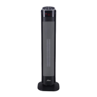
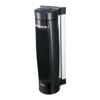
Parts of the Heater
1.
2. LED Display
3. Safety Grille
4. Base
5. Remote Control
6. Power Light
Control Panel
Symbols
(Figure 2)
Power Button
H/L Heat Button
Oscillation Button
Plus Button
Minus Button
Timer Button
Figure 2
(Figure 1)
Figure 1
5
2
3
1
4
6
Temperature Setting Button
1. Unscrew three (3) locking screws from the bottom of the heater
body (Figure 3) and save them.
2. Align two screw bosses and boss holes on back of two halves
of base according to Figure 4.
3. Press two halves of the base, as in Figure 5, to interlock them
together. (Figure 5)
4. Align power cord to the slot on the top side of the base. (Figure 6)
5. Secure the base to the heater body with the locking screws from
Figure 3. Tighten the locking screws firmly with a screw driver.
(Figure 7)
Figure 3
Figure 6 Figure 7
Figure 4
Screw
Bosses
Boss
Holes
81614-01 R20200301
Figure 5
 Loading...