Do you have a question about the Hunter Bandit 2000C and is the answer not in the manual?
Details the amplifier's performance, frequency coverage, and power output capabilities.
Describes the type and number of zero bias triodes used in the amplifier.
Explains the self-contained solid-state voltage doubler power supply circuit.
Explains the pi matching network for antenna impedance matching.
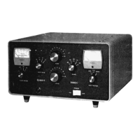
Describes the front panel meters for plate current/voltage and wattmeter.
Lists the front panel controls available on the unit.
Details the connection points available on the rear panel.
Explains connections between exciter, Bandit, and antenna system.
Details power requirements and voltage conversion for operation.
Explains the operation of the grounded grid RF amplifier section.
Details the full-wave voltage doubler power supply circuit.
Describes the wattmeter circuit and its function in measuring output power.
Explains the automatic antenna changeover relays and their function.
Lists recommended preparations and tools before starting assembly.
Provides detailed steps for achieving good solder joints.
Describes the characteristics of a proper solder joint.
Locating and mounting initial components on the chassis and support.
Identifying and preparing components for the printed circuit board.
Mounting components onto the front and back-up panels.
Connecting various wires, relays, and terminal boards.
Installing the AC power switch and wiring control circuits.
Mounting and wiring the auxiliary antenna loading switch components.
Preparing and wiring meter switches and connecting front panel components.
Mounting final components, setting knobs, and aligning panels.
Wiring band switch connections, RF chokes, and capacitors.
Preparing and connecting various cables and wires.
Wiring fan connections and transformer leads.
Installing line cord and making final component connections.
Instructions for initial checks before applying power.
Procedure for applying power and verifying initial readings.
Critical warnings regarding high voltage and discharge procedures.
Instructions for attaching feet and placing the chassis.
Guidance on unit placement for adequate air circulation.
Specifications for exciter output impedance and antenna impedance.
Instructions for connecting the Bandit to transceiver and antenna.
Recommended initial settings for band switch and tuning controls.
Steps for powering on the unit and setting exciter output.
Procedure for adjusting tuning and load controls for maximum output.
Important safety warning regarding tuning with full power.
Recommended plate current levels for SSB operation.
Recommendations for limiting input power during CW operation.
General checks for wiring, solder joints, filaments, and debris.
Comparing voltage readings and safety precautions during measurement.
Guidance for resolving specific problems like TVI and referring to tables.
Procedure for contacting the manufacturer for assistance.
Instructions and considerations for returning the unit for repair.
Procedure for requesting faulty components from the manufacturer.
Details on replacement policy and exclusions for damaged parts.
Details the warranty period and coverage for defects.
Outlines limitations, exclusions, and void conditions for the warranty.