7-
2
Important Note:
Occasionally, the signatures of ICs may exhibit discontinuities or fuzziness due
to oscillation. Most often this occurs in the zener or avalanche breakdown region
of the signature. To obtain a more stable signature, simply reduce the selected
test voltage.
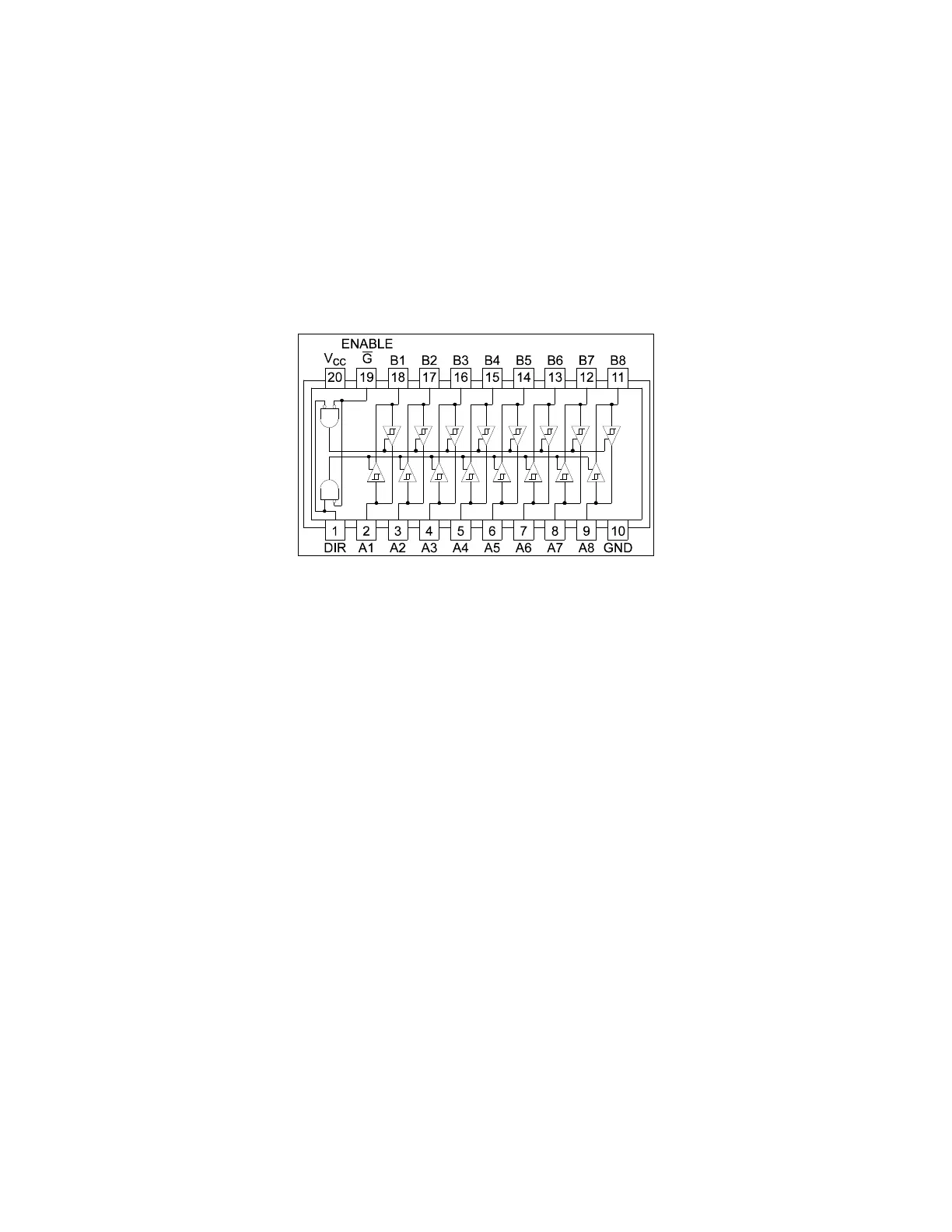
Digital Integrated Circuit Signatures
Before we examine the Tracker signatures of an IC, let's study the block diagram of a 74LS245
octal bi-directional bus buffer to introduce some basic concepts. This IC is a member of the low
power Schottky transistor-transistor logic family (LSTTL). Examine the block diagram for this chip
below. You will see that there are only four different kinds of circuits on this chip.
Figure 7-1. Digital IC 74LS245 Block Diagram
• Circuit 1 - Pins 2 through 9 and 11 through 18 are all the same function. Each pin is
connected to both an input and an output of a buffer.
• Circuit 2 - Pins 1 and 19, although they have different names, are both enables and are
inputs to AND gates.
• Circuit 3 - Power supply ground input, pin 10.
• Circuit 4 - Power supply V
CC
input, pin 20.
Each circuit type will produce a different Tracker signature. Because there are only four types of
circuits on the chip, there will be only four unique Tracker signatures when out of circuit.
 Loading...