7-
17
Buffer pins Enable pins V
CC
Power pin
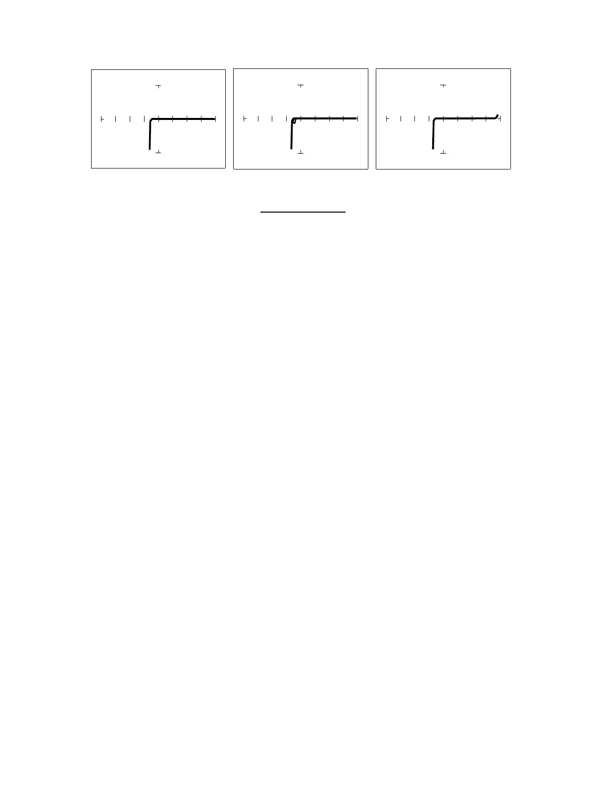
3V, 10 kΩ
ΩΩ
Ω Range
Figure 7-18. Signatures Of A Low Voltage IC (74LVQ45 Type).
Ground Pin To Test Common
The 3V test range (100 kΩ
ΩΩ
Ω , 10 kΩ
ΩΩ
Ω, 1 kΩ
ΩΩ
Ω, 100Ω
ΩΩ
Ω) has been developed to enhance the resistive
fault signatures that are commonly found when troubleshooting this logic family. The test signal
voltage V
S
is lower to ensure that the most descriptive signature is displayed. A higher V
S
may
result in a signature going toward a short which would mask out flaws. The short signature can
be attributed by the LV family's lower voltage characteristics.
Compare these signatures with the CMOS logic family and other discrete components such as
transistors and diodes. Note that these signatures have some common similarities with the other
component Tracker signatures we have seen already.
Review
• Integrated circuits are complex devices that are built using basic electronic components.
• The IC signatures resemble regular and zener diode signatures.
• There are many causes for IC failures and the Tracker 2700 can display its "health" as
resistive leakage, an open or a short.
• Functionally identical pins on a single IC out-of-circuit will display the same signature.
• The most common point for reference is ground, but V
CC
or another point might give a more
informative signature.
• To simplify the large number of signature variations, use the comparison test strategy with
the Tracker 2700. The Tracker 2700 features alternate switching and simultaneous display of
the A and B channels to allow comparison of two individual signatures.
 Loading...