5-
14
Effect of Resistance (R
s
) on the Signature of a 1µF Capacitor
R
S
= 1kΩ
ΩΩ
Ω R
S
= 10kΩ
ΩΩ
Ω R
S
= 100kΩ
ΩΩ
Ω
15 V Range, F
s
= 60Hz
Figure 5-18. Signatures of a 1µF Capacitor at Different Internal Resistances
As the Tracker 2700's internal resistance R
S
increased, the capacitor's signature changes from a
horizontal elliptical pattern to a vertical elliptical pattern.
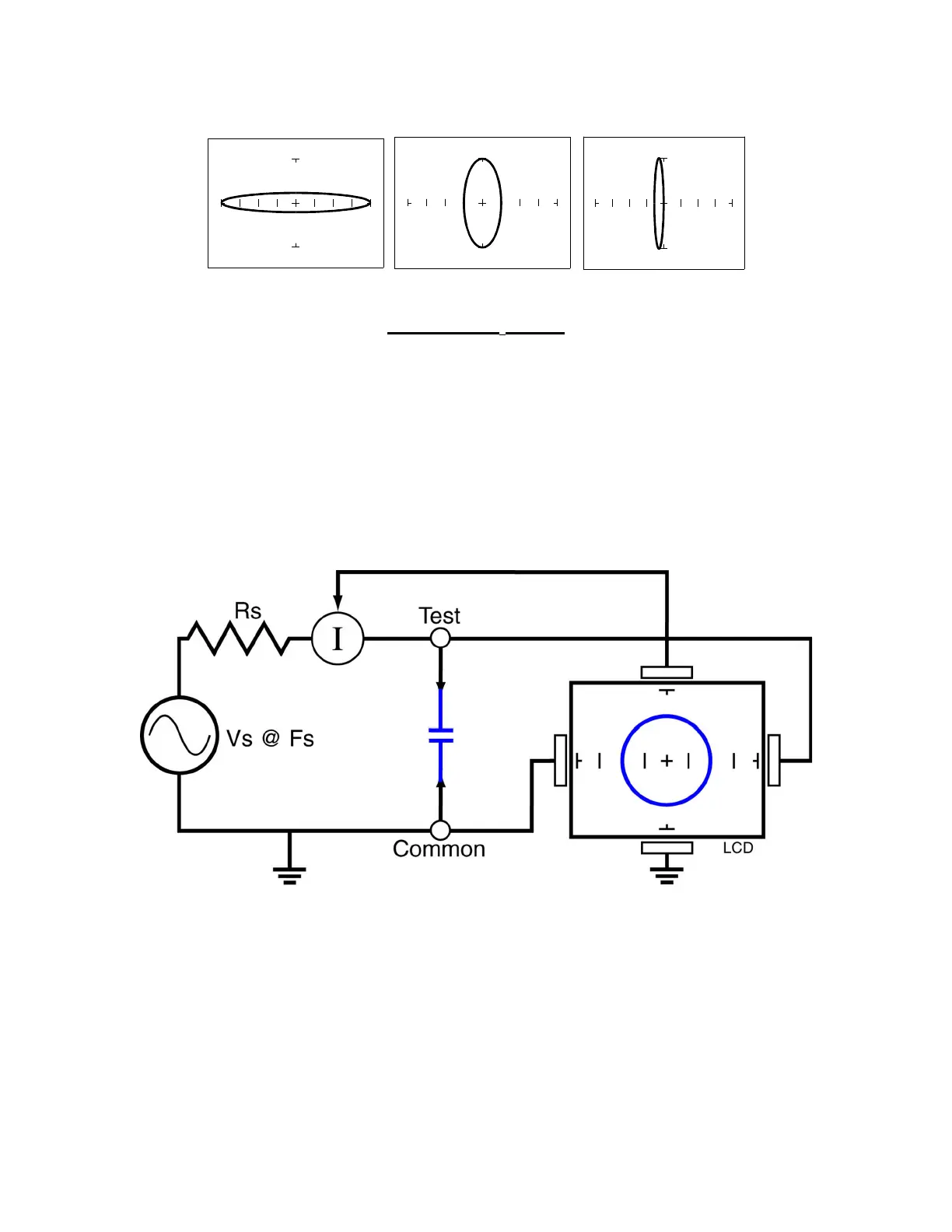
Understanding Capacitor Tracker Signatures
Figure 5-19. Tracker Core Circuit Block Diagram with a Capacitor.
The Tracker 2700 LCD displays as a response to its test signal, a tracker signature that
represents the relationship between voltage, current and resistance of a component. For circuits
that contain capacitors, the effective resistance is called capacitive reactance, X
C
. The
mathematical formula is: