6-
16
Bipolar Transistor Base-Collector Signatures
1. Select the 15V, 10kΩ
ΩΩ
Ω range.
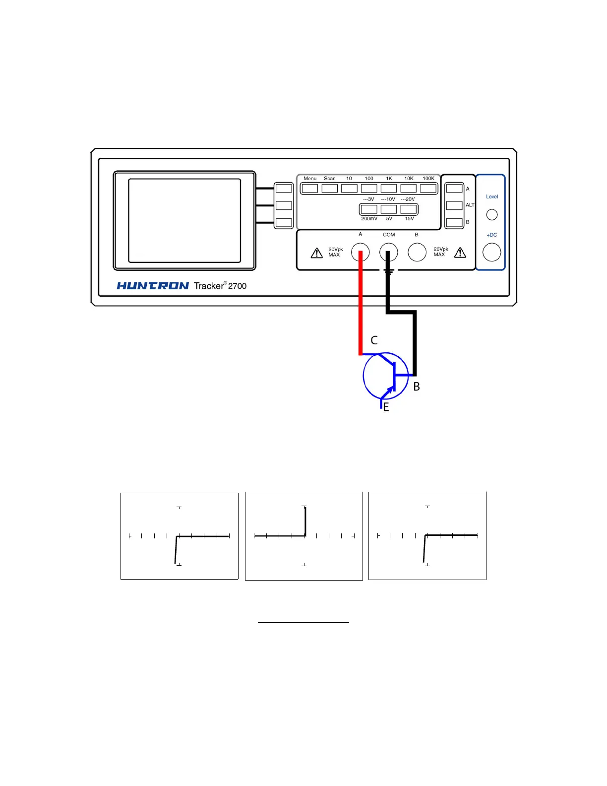
2. Place or clip the red test lead from the Tracker 2700's A test terminal to the Collector lead of
the transistor.
3. Place or clip the black test lead from the Tracker 2700's Common terminal to Base lead of the
transistor.
Figure 6-21. Tracker 2700 Connected to the Collector and Base Leads of a
Transistor
Diode 1N914 PNP Transistor 2N3906 NPN Transistor PN2222A
15V, 10kΩ
ΩΩ
Ω Range.
Figure 6-22. Signature of a Diode and Collector-Base of a Transistor
Notice that the collector-base signature of a NPN transistor is identical to the signature of diode.
The collector-base signature of a PNP transistor, which has opposite polarity from a NPN, looks