6-
26
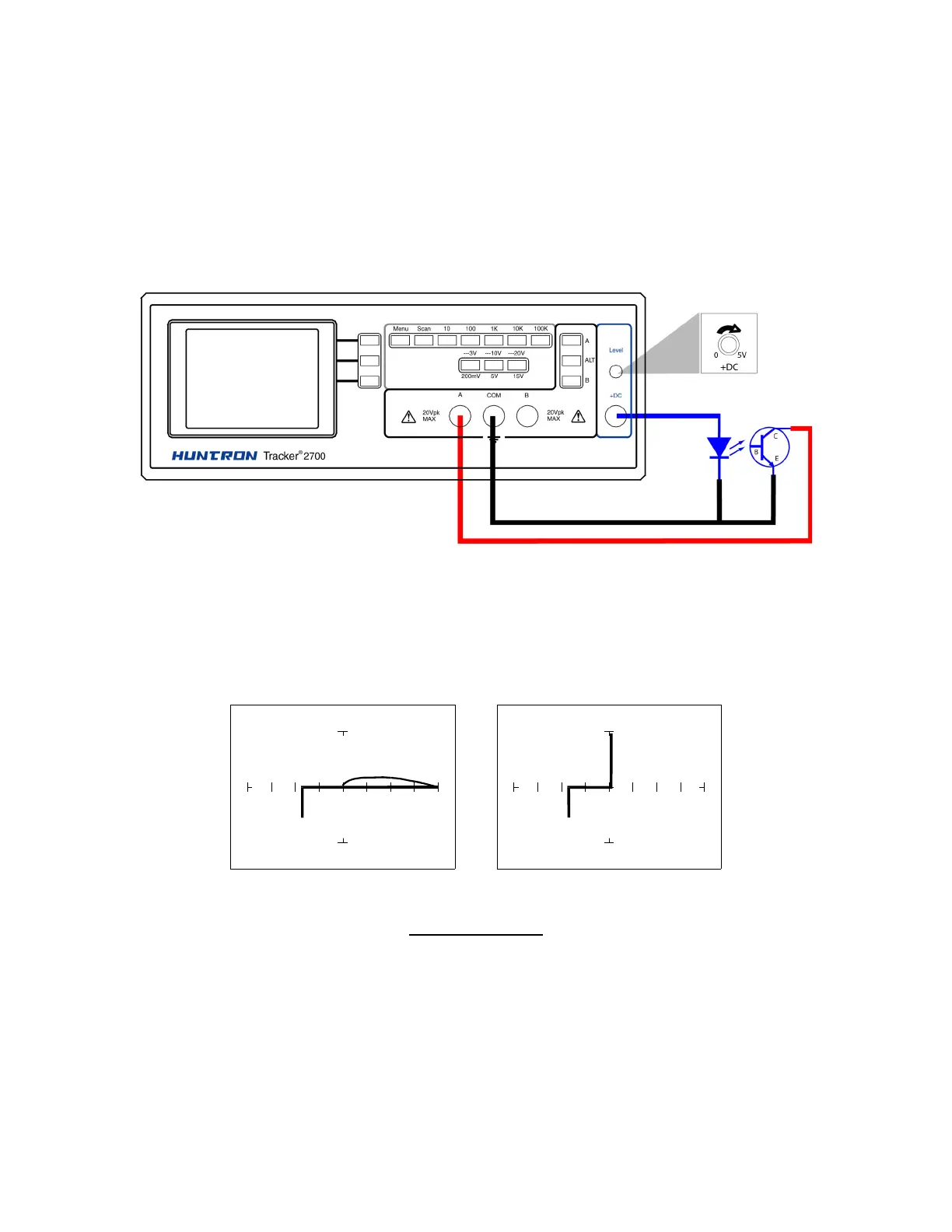
Optocoupler Signatures
1. Select the 10V, 1kΩ
ΩΩ
Ω range.
2. Connect the black test lead or easy grabber from the Tracker 2700's Common test terminal to
the transistor emitter lead and the diode cathode lead of the optocoupler.
3. Connect the red test lead or easy grabber from Tracker’s A to the transistor collector lead.
4. Connect the DC Source +DC output using the blue easy grabber test clip to the diode anode
lead.
Figure 6-34. DC Source test for Optocoupler
Rotate the DC level knob all the way counter-clockwise to start at 0 V DC.
1. Rotate the knob clockwise to approximately halfway.
DC Level = 0V DC level = 5V
10V, 1 kΩ
ΩΩ
Ω Range
Figure 6-35. Signatures of an Optocoupler - 4N33 Type