AllProductslimitedtoVehicleTowRating,Seewww.huskytow.comforWarrantyInformation/TechSupport/Product
Updates.©2018LKQSPG.AllRightsReserved.Nov.16,2018‐Rev11 Page‐4
5. Place the two bed rails across the truck bed between the wheel wells. Position the 5
th
wheel uprights between the bed rails
so that the tabs in the base of each upright will fit into the slots in the ends of the bed rails. Secure the uprights n place with
the rail hitch pins and hair pins supplied with the 5
th
wheel installment kit. Securely attach 5
th
wheel cross member to
uprights.
6. Position the bed rail assembly in truck bed as shown on the layout illustration on page 2 of this instruction sheet. When
hitch is correctly positioned in the bed and the bed rails are parallel, mark four attachment points on the truck bed using the
5/8” square holes indicated on the layout Illustration on Page 3 of this document.
7. Check below the bed before drilling holes to see that all wiring, brake lines or other obstructions are moved out of the way
and will not be contacted by the drill. Drill 1/4” pilot hole through bed floor at each previously marked location. Check to see
that these holes line up with installed frame bracket mounting tabs. Adjust hole location as needed. Move the hitch
assembly out of the way and drill four 5/8” diameter attachment holes down through the bed at the previously marked
points.
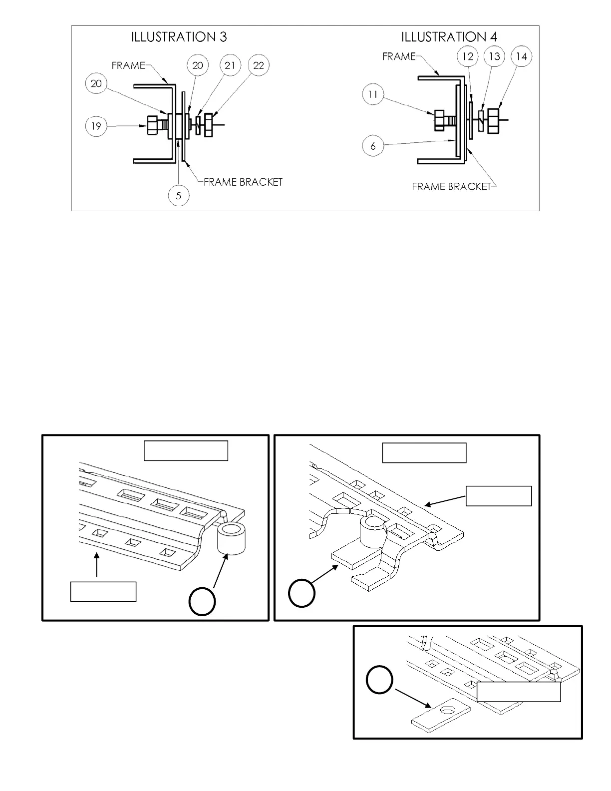
8. Reposition the bed rails in the bed so that the square 5/8” hole in the end of each rail is lined up over the drilled holes.
Place a 1” spacer tube (#4) under ends of each bed rail, in line with the drilled holes. See Illustration 5.
9 If the bed corrugation above the frame bracket is UP, leaving a
space above the frame bracket, place a spacer plate (#3) in this
location as shown on Illustration 6. If the corrugation is DOWN,
at this location, place a spacer plate (#3) in the bed, under the
base rail as shown on Illustration 6a. Bolt parts loosely in place
as shown on Illustration 7
Illustration 5
Illustration 6
Illustration 6A
4
3
3
Base Rail
Base Rail
 Loading...