24
SERVICE AND ADJUSTMENTS
TRANSMISSION REMOVAL/REPLACEMENT
Should your transmission require removal for service or
re place ment, it should be purged after reinstallation and
before op er at ing the tractor. See “PURGE TRANS MIS SION”
in the Operation section of this manual.
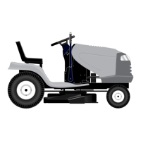
FIG. 26
2498
ENGINE PULLEY
02504
RETAINER
SPRING
DRIVE BELT TENSION
HANDLE
BELT KEEPER
BELT
KEEPER
V-IDLER
CLUTCHING
IDLER
CLUTCHING
FLAT IDLER
BELT
KEEPER
FLAT IDLER
TRANSAXLE
PULLEY
TRANSAXLE MOTION CONTROL LEVER
NEUTRAL ADJUSTMENT (See Fig. 27)
The motion control lever has been pre set at the factory and
adjustment should not be necessary.
• Park tractor on level surface. Stop tractor by turning
ignition key to “OFF” position and engage park ing
brake.
• Loosen the adjustment bolt in front of the right rear
wheel.
• Move motion control lever to the neutral position (N).
• Tighten the adjustment bolt.
FIG. 27
AD JUST MENT
BOLT
02508
TO REPLACE MOTION DRIVE BELT
(See Fig. 26)
Park the tractor on level surface. Engage parking brake.
For ease of service there is a belt installation guide decal
on bottom of left footrest.
• Remove mower (See “TO REMOVE MOWER” in this
section of this manual.)
BELT REMOVAL -
• Create slack in belt by removing retainer spring from
drive belt tension handle.
• Remove belt from all idler pulleys, transaxle pulley and
then from engine pulley.
BELT INSTALLATION -
• Install new belt around engine pulley fi rst, then around
transaxle pulley and lastly into all the idler pulleys.
• Check to be sure belt is positioned correctly and is on
proper side of all belt keepers.
• Engage the drive belt tension handle and replace the
retainer spring.
• Reinstall mower.
BELT
KEEPER
RE TAIN ING
RING
WASH ERS
FIG. 28
AXLE
COVER
TO REMOVE WHEEL FOR REPAIRS
FRONT WHEEL (See Fig. 28)
• Block up axle securely.
• Remove axle cover, retaining ring and washers to allow
wheel removal.
• Repair tire and reassemble.
• Replace washers and snap retaining ring securely in
axle groove.
• Replace axle cover.
REAR WHEEL -
• Block rear axle securely.
• Remove fi ve (5) hub bolts to allow wheel removal.
• Repair tire and reassemble. Replace and tighten hub
bolts securely.
NOTE: To seal tire punctures and prevent fl at tires due to
slow leaks, tire sealant may be purchased from your local
parts dealer. Tire sealant also prevents tire dry rot and
corrosion.
TO START ENGINE WITH A WEAK BAT TERY
(See Fig. 29)
WARNING: Lead-acid batteries gen-
er ate ex plo sive gases. Keep sparks,
fl ame and smoking ma te ri als away from
bat ter ies. Always wear eye pro tec tion
when around batteries.
If your battery is too weak to start the engine, it should be
recharged. (See "BATTERY" in the Maintenance sec tion
of this man u al).
If “jumper ca bles” are used for emer gen cy starting, follow
this pro ce dure:
TO AD JUST STEER ING WHEEL ALIGN-
MENT
If steering wheel crossbars are not horizontal (left to right)
when wheels are positioned straight forward, remove steer-
ing wheel and reassemble per instructions in the Assembly
section of this manual.
FRONT WHEEL TOE-IN/CAMBER
The front wheel toe-in and camber are not adjustable on
your tractor. If damage has occurred to affect the front
wheel toe-in or camber, contact your nearest authorized
service center/department.
 Loading...