The Hy-Range III Model 672B is a 23-channel solid-state 5-watt mobile Citizens Two-Way Radio, designed and licensed for Class D Citizen Band operation as designated by the Federal Communications Commission (F.C.C.). This compact and completely solid-state unit offers high reliability and low power consumption, making it suitable for mobile installations in vehicles such as cars, trucks, and boats.
Function Description:
The primary function of the Hy-Range III is two-way radio communication on the 23 channels of the 27 MHz Citizens Band. It utilizes an advanced frequency synthesization system, allowing immediate operation on all channels without the need for additional crystals or adjustments. The transceiver is designed to operate from 11.5 to 14.5 volts DC.
Beyond standard two-way communication, the unit also features a public address (PA) system. This allows the microphone and the internal audio stages of the transceiver to be used to project sound through an external PA speaker, which can be mounted on the exterior of a vehicle or building.
Usage Features:
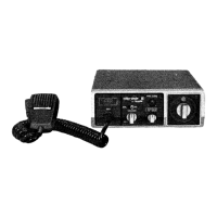
The front panel of the Hy-Range III is equipped with several controls and indicators for easy operation:
- Power/Volume Switch: This knob controls the power to the unit and adjusts the sound output from the speaker. Rotating it clockwise turns the power on and increases volume, while rotating it counterclockwise turns the power off.
- Squelch Control: This control eliminates annoying background noise when no signal is present. To adjust, the user turns the knob counterclockwise until background noise is heard, then slowly clockwise until the noise disappears. This allows for varying degrees of sensitivity to incoming signals; turning it fully counterclockwise disables the squelch circuit for receiving very weak signals.
- RF Gain Control: This knob adjusts the RF gain (reception sensitivity) when receiving. Turning it clockwise increases RF gain, and counterclockwise decreases it.
- Channel Selector: A continuously rotating switch allows the user to select any of the 23 channels for transmit and receive operation. It also includes a "PA" position for engaging the public address system.
- Fine Tuning: This control enables adjustments for clear reception of stations that may be operating slightly off frequency. The user rotates the knob for clearer reception.
- ANL/NB (Noise Blanker) Switch: This switch provides noise suppression capabilities. In the ANL (Automatic Noise Limiter) position, it reduces atmospheric-type noises. In the NB (Noise Blanker) position, both ANL and NB circuits are active, suppressing pulse-type interference, such as ignition noise, by momentarily turning off the receiver. The effectiveness of the blanker can be influenced by the signal strength of nearby stations.
- Signal Strength/RF Power Meter: This built-in meter provides a relative indication of signal strength in "S" units during reception (upper scale) and an indication of antenna RF power during transmit (lower scale). When transmitting, the pointer should flicker slightly with voice modulation.
- Modulation Lamp: This lamp illuminates when the push-to-talk button on the microphone is pressed and flickers with voice during transmission, indicating modulation.
- Receiver Lamp: This lamp lights up when the transceiver is in the receive mode.
- Microphone Jack: This is where the push-to-talk microphone or an optional telephone handset is connected.
For CB Transmitter Operation, the user connects the microphone, selects a desired channel, and depresses the push-to-talk button while speaking 4 to 6 inches from the mouth at a normal level. The receiver is silenced during transmission. To receive, the push-to-talk button is released.
For Public Address Operation, an external 8-ohm PA speaker is connected to the PA jack on the rear panel. The CB channel selector is set to the "PA" position, and the push-to-talk button is pressed to speak into the microphone. The volume control on the transceiver also adjusts the PA speaker output.
Maintenance Features:
The manual emphasizes several aspects related to the maintenance and longevity of the device:
- Installation Considerations: Proper installation is crucial. The transceiver should be mounted in a convenient location that does not interfere with driving. The provided mounting bracket can be used for base or gimble type overhead mounting, secured with screws or bolts.
- DC Power Connections: The Hy-Range III can operate from a nominal 12 VDC battery source on both negative and positive ground systems. Users must determine their vehicle's ground system before connecting the red lead to the positive side and the black lead to the negative side of the electrical system. Specific connection points for negative and positive ground vehicles (e.g., accessory post on ignition switch, ammeter, fuse block, metal firewall) are detailed.
- Antenna Connection: The antenna must be connected to the transceiver via coaxial cable (RG-58/u or RG-8/u) terminated with a PL-259 connector. A critical caution is provided: Do not transmit without an antenna connected to the transceiver to prevent damage.
- Noise Suppression: The manual provides extensive guidance on noise suppression, particularly for mobile installations where ignition noise is common.
- Tune-up: Before specific noise suppression steps, the vehicle should be well-tuned. This includes cleaning and tightening electrical connections (alternator, battery, regulator, coil), soldering crimped spark plug/distributor leads, cleaning/regapping/replacing spark plugs and ignition points, and checking/cleaning alternator rings or generator brushes.
- Corrective Steps: Detailed steps are provided to identify and eliminate various noise sources:
- Ignition Noise: Install resistor-type spark plugs, 10 k-ohm suppressor resistors at spark plug towers, and a coaxial capacitor at the ignition coil primary.
- Alternator Whine: Check and clean the alternator, and install an alternator filter.
- Voltage Regulator Noise: Install a 4-ohm carbon resistor and a 0.002 µF capacitor in series near the field terminal of the regulator.
- Static Discharge: Tighten loose nuts and bolts, and bond large areas (fenders, exhaust pipe, firewall) to the frame with heavy wire braid.
- The manual also references the "Radio Amateur's Handbook" for additional information on noise suppression.
- Warranty and Servicing:
- The device comes with a 90-day limited warranty covering defective material and workmanship under normal use.
- Users are advised to contact their Hy-Gain dealer or service center for warranty repairs and to obtain a Class D Citizen Band license before transmitting.
- It is explicitly stated that it is illegal to transmit without a license and prohibited to adjust transmitter circuits without a current First or Second Class Radiotelephone License.
- Tampering with internal adjustments or settings is discouraged as it can adversely affect performance and may cause the unit to operate beyond FCC limitations.
- For returns, all requested information should be included, and the unit should be well-packed and insured to prevent damage during shipment.
- Parts can be purchased from the factory's Customer Service Department, requiring the model number, serial number, part description, and part number.
- The warranty is void if the equipment has been modified, improperly installed, or misused. Hy-Gain reserves the right to make design improvements without obligation to update previously manufactured products.