P a g e 19 | 38
Chapter III
Installation & Assembly
Installation
Vertical installation of the UV housing vessel (in the horizontal pipeline) must be observed.
Water isolation valves should be fitted either side of the unit. If site require continuous water
supply to the building during maintenance works and no down time is required, then a suitable
by-pass should be fitted. By-pass should be suitably arranged to minimise dead legs.
Minimum of 500mm clearance above the unit is required for lamp exchange and cleaning
purposes.
If a UV unit is to be installed around a booster pump set, it must be sited on the outlet side of
that pump.
Some level of water flow through the UV chamber is required at all times. This is to ensure that
the UV lamp doesn’t overheat.
Suitable pre-filtration unit should be installed prior of the UV unit to minimize the level of
particulates in the water that may cause shadowing.
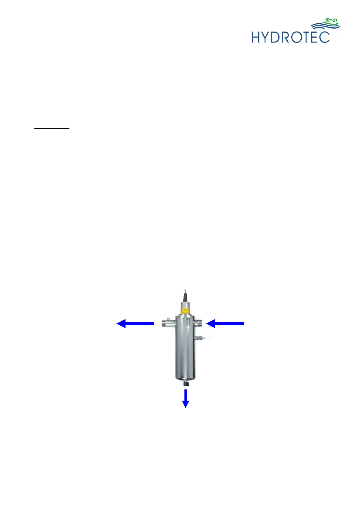
There are flow directional arrows attached at the unit connections for the ease of installation.
Please ensure that there is sufficient space available under the drain valve for drainage.
Free space under the system shall be min. ca. 30 cm.
It is highly recommended that the unit operates and is powered up continuously, 24/7. Switching the
lamp on and off regularly can significantly reduce the life span of the lamp.