Do you have a question about the Hygood FM-200 and is the answer not in the manual?
Comprehensive guide for FM-200® system design, installation, and maintenance.
Overviews FM-200® as a fire suppressant and its advantages over Halon.
Lists approvals and standards for FM-200® agent use, including FM Approved.
Discusses precautions and understanding of agent effects for personnel safety.
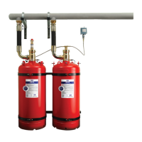
Details the container assembly, its factory filling, and pressurization.
Describes the container valve, its safety features, and components.
Describes manifolds as fabricated pipe sections for connecting multiple containers.
Distributes agent within the protected area, sized for correct flow.
Measures liquid FM-200® level in containers for weight determination.
Outlines the two main elements: risk assessment and quantity calculation.
Describes the hazard survey process, including risk assessment and environmental factors.
Explains how to determine hazard volume and the impact of openings and obstructions.
Advises on avoiding exposure to FM-200® and potential hazards.
Factors to consider for choosing and placing discharge nozzles for coverage.
Specifies elevation differences and distances for pipe runs and nozzles.
Outlines the step-by-step process for designing FM-200® systems.
Demonstrates calculating minimum agent quantity using a formula.
Formula for calculating agent weight based on hazard volume and concentration.
Systems based on Hydraulic Flow Program for predicting two-phase flow.
Container location requirements and securing methods.
Step-by-step instructions for installing single containers.
Checks to be made before final connections, including mechanical and electrical.
Thorough inspection of system completeness, tests, and operational status.
Describes the door fan test method and its components.
Measuring ELA by blowing air to develop pressure differential.
Steps for evaluating enclosure readiness, volume confirmation, and retention time.
Describes manual, fully automatic, and automatic with manual intervention systems.
Automatic release based on multiple sensor detection with adjustable time delay.
Explains decomposition at high temperatures and the formation of toxic products.
Advises emergency services, organizes roll-call, and prevents unauthorized entry.
Provides user inspection and maintenance guidance for FM-200® Engineered Systems.
Installer provides inspection program to detect faults early.
System inspection and testing by qualified personnel as per NFPA standards.
Procedures for weighing containers to establish FM-200® content.
Device used to determine FM-200® liquid level and agent weight.
Steps for measuring liquid FM-200® level using the measuring device.
Detailed procedure for servicing actuators and pilot actuation lines.
Procedures for refilling discharged containers by the Original Equipment Manufacturer.
Operations carried out on containers requiring recharging and valve refurbishment.
Valve assembly tests including pre-dome and leak tests after refurbishing.
Procedures for filling containers at UL and FM stations, including scale checks.
Leakage test for filled valves and container assemblies after 24 hours standing.
| Brand | Hygood |
|---|---|
| Model | FM-200 |
| Category | Security Sensors |
| Language | English |