TORCH LEAD REPLACEMENT
Field Service Bulletin 7
7. Lay the right side of the handle on a flat surface.
8. Position the pilot wire, cap sensor wires, and cap sensor wire connector in the handle. Press the cap sensor switch
onto the mounting post in the handle while pressing the cap sensor post into the post hole in the handle.
9. Gently press the torch body into the torch handle with the gas hose fitting’s flange aligned with the slot in the
handle. Be careful not to damage the cap sensor, cap sensor wires or pilot wire in the handle. Make sure that the
strain relief rests in the slot near the rear of the handle.
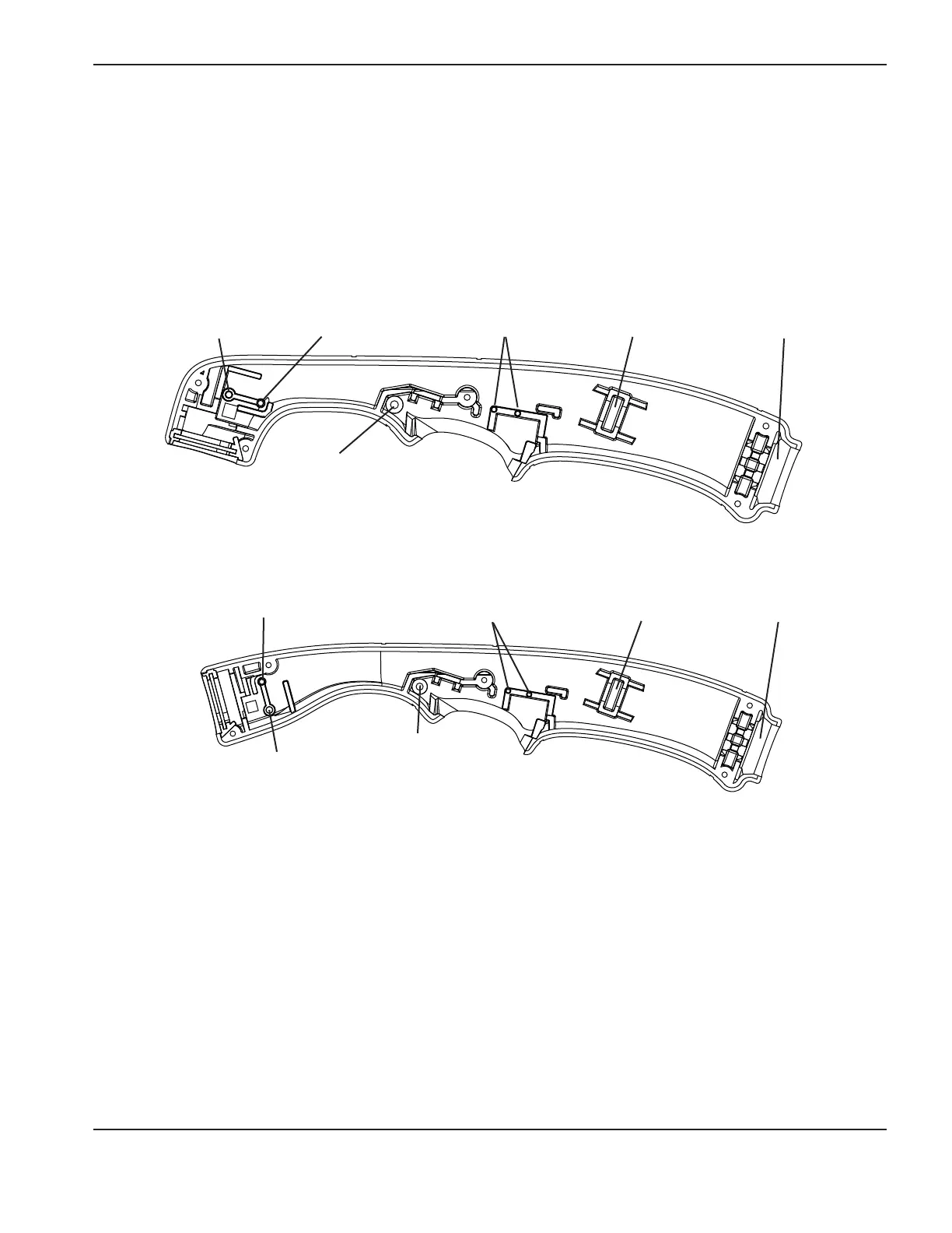
Duramax 75°/HRT/HRT
2
Duramax 15°/HRTs
Start switch posts
Cap sensor switch
mounting post
Cap sensor
switch post hole
Trigger’s pivot hole
Strain relief slot
Gas hose fitting slot
Gas hose fitting slot
Start switch posts
Cap sensor switch
mounting post
Cap sensor
switch post hole
Trigger’s pivot hole
Strain relief slot
 Loading...
