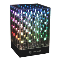
Hypnocube 4Cube Instructions v 6.5, December 2013
- 52 -
Appendix 4: Programming your cube
You can find detailed information on drawing to the cube from a PC program via the USB module in a
companion manual available on the Hypnocube website. We released detailed specs on the protocol to talk to
the PIC, sample C++ source code, and a sample program to fiddle with the Hypnocube settings.
But for those who really want to get their hands dirty and reprogram the PIC microcontroller with their own
code, here are some things to get you started.
DISCLAIMER: REPROGRAMMING THE PIC IS NOT SUPPORTED. YOU DO SO AT YOUR OWN
RISK! WE WILL NOT RELEASE OUR SOURCE CODE OR THE HEX FILE FOR THE CUBE, SO IF YOU
ERASE YOUR PIC IT CANNOT BE RESTORED. WE HIGHLY RECOMMEND SOCKETING THE PIC
AND USING A SPARE PIC, LEAVING THE ORIGINAL PREPROGRAMMED PIC UNTOUCHED.
We have found that the Aries Series 526 low profile ZIF socket fits on the PCB as allows enough clearance to
insert and remove the PIC from underneath the LED lattice with a bit of care. Another approach made by one
customer was to place a socket on the bottom of the PCB, and bend all of the PICs pins up to maintain the
proper connections. We can’t be responsible for broken pins, but it worked for him!
The pins for the low voltage in-circuit programmer are broken out on the PCB (labeled LV-ICP). To connect a
programmer you will need to look up the PIC18F4620 docs and see how the pins are exported from our PCB.
Don’t ask us for help beyond this – though perhaps eventually we will have forums with questions and answers
for hackers working on these items.
The PIC programmer we used is the simple circuit and PicPGM software freely available from
http://www.members.aon.at/electronics/pic/picpgm/.
The UART is available and broken out on a header, and you can also re-appropriate the 2 GPIO pins used for
the buttons for other purposes if you wish.
This PCB, circuit, and PIC controller can give you a nice platform for a whole host of LED related projects.
Basically you can use it to drive 64 3-color LEDs in any configuration you like, or 192 single color LEDs in any
pattern you desire. The hardware allows individual pixel and color access, and with time multiplexing, you can
even get many levels of color.
 Loading...