This document is a service and repair manual for Hyster Internal Combustion Engine Trucks, specifically models B236 (H400HD, H450HD, H400HDS, H450HDS) and related variants. The manual focuses on the transmission repair for TE13 and TE17 transmissions, which are integral components of these heavy-duty lift trucks.
Function Description:
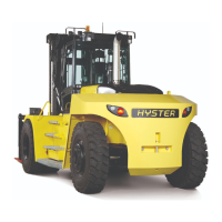
The Hyster B236 series of lift trucks are internal combustion engine-powered vehicles designed for heavy lifting and material handling applications. The core function of these trucks is to transport and lift heavy loads in various industrial environments. The transmission, specifically the TE13 and TE17 models covered in this manual, is responsible for transmitting power from the engine to the drive wheels, allowing the truck to move, change speeds, and reverse. The TE13 and TE17 transmissions are designed for robust performance in demanding conditions, facilitating the precise control and power delivery required for heavy-duty operations. The TE13 transmission is typically fitted on trucks with a 142 kW engine option, while the TE17 is used with the 164 kW engine option, indicating their suitability for different power outputs and load capacities.
Important Technical Specifications (as inferred from the document):
- Transmission Models: TE13 and TE17.
- Engine Power Compatibility: TE13 for 142 kW engines; TE17 for 164 kW engines.
- Truck Models Covered:
- H16.00-18.00XM/XMS-12 (H400-450HD/HDS) [A236]
- H16.00-22.00XM-12EC (H400-500HD/HDS-EC) [B214]
- H16XM-12, H18XM-12, H20XM-12, H22XM-12 (H400HD, H450HD, H500HD, H550HD) [B236]
- H16XM-12EC, H18XM-12EC, H22XM-12EC (H400HD-EC, H450HD-EC, H500HD-EC) [C214]
- Key Transmission Components: Torque converter, multiple clutch drums (1st, 2nd, 3rd, Forward, Reverse), output shaft, stator support, pump drive gears (idler and main), control valve assembly, various bearings, seals, and gaskets.
- Lifting Capacity Requirement for Transmission Removal: A lifting device with a minimum capacity of 1000 kg (2205 lb) is required to safely remove the transmission.
- Special Tool Dimensions (for FWD/3RD shaft assembly): Ø52.50 mm (2.07 in) diameter, 90 mm (3.54 in) height, 470.46 mm (18.52 in) overall length. This tool is crucial for preventing gear drop during transmission manipulation.
- Clutch Design: The difference between TE13 and TE17 models also includes the number of discs in the clutches, suggesting variations in torque capacity and power handling.
- Torque Converter: An essential part of the transmission, responsible for fluid coupling between the engine and the gearbox. The manual details its removal and disassembly.
Usage Features (implied from repair procedures):
- Heavy-Duty Application: The truck models and transmission types indicate use in environments requiring significant lifting and robust operation, such as construction sites, ports, or large warehouses.
- Internal Combustion Engine: These trucks are powered by internal combustion engines, requiring fuel (Gasoline, LPG, CNG, Diesel) and associated fuel system maintenance.
- Hydraulic System Integration: The transmission interacts with hydraulic pumps, which are disconnected and removed during transmission servicing, indicating an integrated hydraulic system for various truck functions (e.g., mast operation, steering).
- Electronic Control: The presence of engine speed, temperature, and drum speed sensors, along with wiring harnesses, suggests electronic control and monitoring of the transmission's operation.
- Drive Plate Connection: The transmission connects to the engine via a drive plate and flywheel, which must be carefully handled during removal to prevent damage.
Maintenance Features:
The manual is primarily a guide for detailed maintenance and repair, emphasizing safety and correct procedures.
- Comprehensive Disassembly/Assembly Instructions: Step-by-step procedures are provided for removing, disassembling, cleaning, inspecting, and assembling various transmission components, including:
- Transmission Case
- Clutch Drums (1st, Reverse, 2nd, 3rd, Forward)
- Output Shaft
- Housings
- Oil Seals and Gaskets
- Bearings
- Gears and Shafts
- Control Valve
- Safety Precautions: A dedicated section highlights critical safety measures, including:
- Using proper lifting mechanisms for heavy parts.
- Wearing safety glasses.
- Disconnecting battery connectors before work.
- Using correct blocks to prevent truck movement.
- Keeping the work area clean and organized.
- Using correct and clean tools.
- Using HYSTER APPROVED parts.
- Ensuring all fasteners are removed before forcing parts.
- Attaching "DO NOT OPERATE" tags.
- Following WARNING and CAUTION notes (distinguished by orange/yellow backgrounds).
- Precautions for handling flammable fuels and batteries.
- Cleaning and Inspection: Specific steps are included for cleaning and inspecting components to identify wear or damage, crucial for effective repair.
- Torque Specifications: The manual includes a section for torque specifications for lubricated or plated screw threads, ensuring proper fastening and preventing damage or failure.
- Sensor Management: Instructions for removing and installing engine speed, temperature, and drum speed sensors are provided, indicating the importance of these components for transmission monitoring and control.
- Oil Management: Procedures for draining transmission oil and disconnecting oil lines to the cooler and hydraulic pumps are detailed, emphasizing proper fluid handling.
- Special Tools: The use of special tools, such as bearing pullers and custom-fabricated tools (with specified dimensions), is highlighted for specific tasks, ensuring efficient and damage-free repair.
- Component Identification: The manual provides diagrams and images to aid in identifying components, such as the TE17 transmission front view and sensor locations.
- System Diagnostics: While primarily a repair manual, the mention of "diagnostics" in the general section implies that the detailed component-level information supports troubleshooting efforts.
- Documentation: References to other SRM (Service Repair Manual) documents (e.g., Diagrams 8000 SRM 1312 and 8000 SRM 1281) for electrical system diagrams indicate a comprehensive documentation ecosystem for these lift trucks.