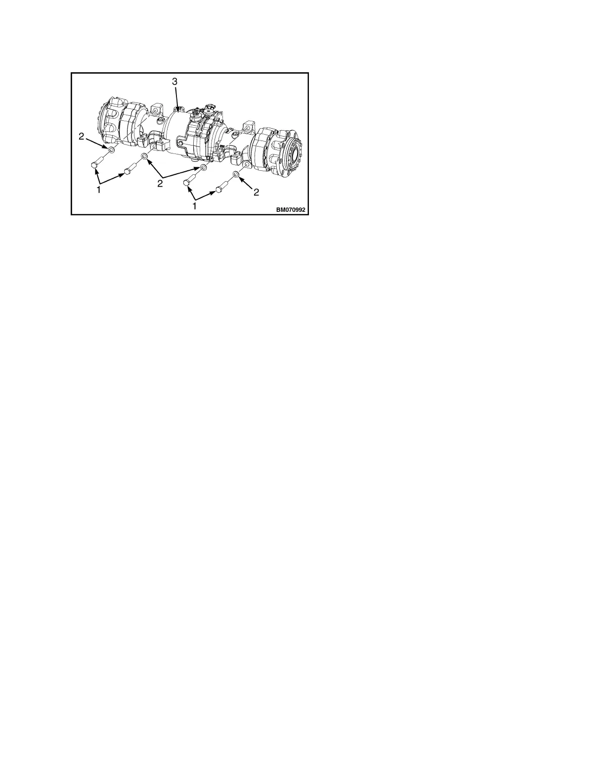
Figure 6. Drive Axle Mounting Capscrews
Legend for Figure 6
NOTE: DRIVE AXLE FOR H4.0FT5/FT6; H4.5FTS5,
H4.5FT6, H5.0-5.5FT (H80, 90, 100, 110, 120FT)
(R005, S005, U005) SHOWN. TRANSMISSION
MOUNTING FOR S4.0, 4.5, 5.5FT, S5.5FTS (S80,
100, 120FT; S80, 100FTBCS; S120FTS;
S120FTPRS) (H004, J004) IS SIMILAR.
1. CAPSCREW
2. WASHER
3. DRIVE AXLE
Reduction Gear Assembly
REMOVE
1.
Remove fourteen capscrews in wheel hub cou-
pler.
See Figure 7 for lift truck models
• S4.0, 4.5, 5.5FT, S5.5FTS (S80, 100,
120FT; S80, 100FTBCS; S120FTS;
S120FTPRS) (H004, J004)
See Figure 8 for lift truck models
• H4.0FT5/FT6; H4.5FTS5, H4.5FT6,
H5.0-5.5FT (H80, 90, 100, 110, 120FT)
(R005, S005, U005)
2.
Install two of fourteen capscrews in wheel hub
removal holes. DO NOT tighten capscrews.
See Figure 9 for lift truck models
• S4.0, 4.5, 5.5FT, S5.5FTS (S80, 100,
120FT; S80, 100FTBCS; S120FTS;
S120FTPRS) (H004, J004)
See Figure 10 for lift truck models
• H4.0FT5/FT6; H4.5FTS5, H4.5FT6,
H5.0-5.5FT (H80, 90, 100, 110, 120FT)
(R005, S005, U005)
3.
Once capscrews are snug, begin an alternating
tightening sequence between two capscrews.
Make sure to turn each capscrew same amount
before returning to previous capscrew. Before
capscrews bottom out, wheel hub coupler will
be freed from wheel hub.
4.
Once wheel hub coupler is free, bearing cap
may be driven free from wheel hub coupler (if it
shows signs of damage) with a soft hammer/
mallet. Discard bearing cap if removed.
5.
Remove two O-rings from wheel hub coupler
and discard.
See Figure 9 for lift truck models
• S4.0, 4.5, 5.5FT, S5.5FTS (S80, 100,
120FT; S80, 100FTBCS; S120FTS;
S120FTPRS) (H004, J004)
See Figure 10 for lift truck models
• H4.0FT5/FT6; H4.5FTS5, H4.5FT6,
H5.0-5.5FT (H80, 90, 100, 110, 120FT)
(R005, S005, U005)
6.
Remove ten capscrews holding retaining plate
to wheel bearing support. See Figure 11.
7.
Rotate wheel hub to access socket head cap-
screws in wheel bearing support.
8.
Remove twelve socket head capscrews in wheel
bearing support. See Figure 12.
9.
Remove reduction gear assembly from drive
axle trumpet arm (left side). See Figure 12.
10.
Remove and discard O-ring. See Figure 12 de-
pending on lift truck model.
1400 SRM 1582 Drive Axle Removal
5
 Loading...