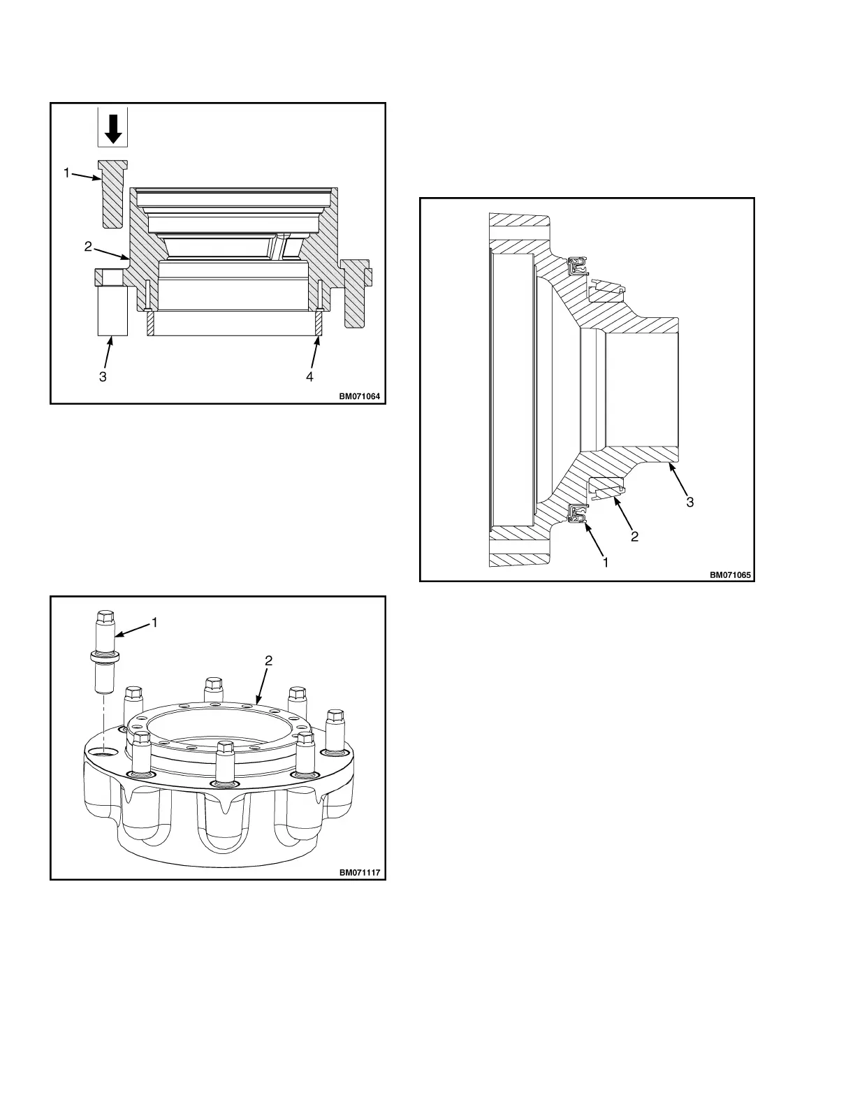
1. WHEEL STUD
2. WHEEL HUB
3. SOCKET OR SPACER
4. STEEL RING, SPACER, OR BLOCKS
Figure 20. Wheel Studs Install for Lift Truck
Models S4.0, 4.5, 5.5FT, S5.5FTS (S80, 100, 120FT;
S80, 100FTBCS; S120FTS; S120FTPRS) (H004,
J004)
Figure 21. Wheel Studs Install for Lift Truck
Models S4.0, 4.5, 5.5FT, S5.5FTS (S80, 100, 120FT;
S80, 100FTBCS; S120FTS; S120FTPRS) (H004,
J004)
Legend for Figure 21
1. WHEEL STUD
2. WHEEL HUB
1. SEAL
2. INBOARD BEARING CONE
3. WHEEL BEARING SUPPORT
Figure 22. Wheel Bearing Support
NOTE: A press or hammer used with appropriate
driver tool will be required for installation of bear-
ings, bearing cones, and bearing cups.
5.
With wheel hub on a flat surface, install a new
inboard bearing cup into wheel hub.
See Figure 23 for lift truck models
• S4.0, 4.5, 5.5FT, S5.5FTS (S80, 100,
120FT; S80, 100FTBCS; S120FTS;
S120FTPRS) (H004, J004)
See Figure 24 for lift truck models
• H4.0FT5/FT6; H4.5FTS5, H4.5FT6,
H5.0-5.5FT (H80, 90, 100, 110, 120FT)
(R005, S005, U005)
Reduction Gear Assembly 1400 SRM 1582
14
 Loading...