Service Manual
6. Front Panel
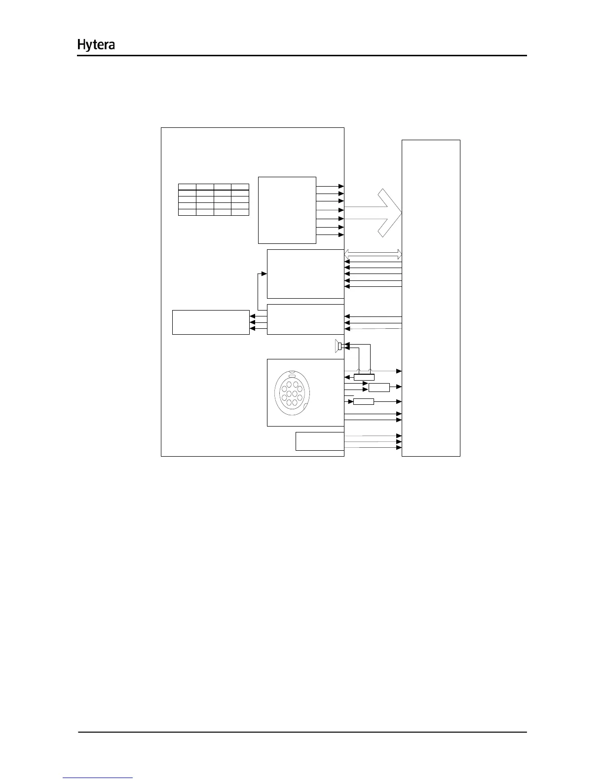
The front panel contains the speaker, keys, power switch, volume control knob, LCD display and other
parts. The block diagram is shown as the figure below.
CONTROL HEAD
BACK LIGHT&
SIGNAL LIGHT
BL_LED
RX_LED
TX_LED
U1
\RESET
SHIFT_CLK
A
QA
QB
QC
QD
Keyboard
R1
R2
R3
C1
C2
C3
LCD
DB[ 0: 7 ]
RESET
\CS
\WR
\RD
LED
GPIO_1 / D+
ACC_ ID
SPK
MIC _GROUND
GPI O3&PTT
GPIO_2 / D-
USB_Vb us
INT_MIC
GPIO_4 / Hook
GPIO_0 / PwrOn
MMP
U7
U302
3*4 KEY
Keyboard
Interface
EMI FS
FLASH.CS2#
RST _OUT
CS
CLOCK
DATA
U231
U231
5VD
SPK+SPK-
GPI O
GPI O
GPI O
Mc B S P
FILTER
USB. DP
USB. DM
FLASH.D
p1
P5
C2
P4
Swit chP3
Me nu
C1
Back P2
Down
C0
R2
R1R0
Keys Matrix
FLASH. A1
FLASH.WE#
FLASH. OE#
RS
A
B
S
UART2
GPI O
EMER
P6
C3
C4
UP
Figure 6-1 Diagram of Front Panel
1) Power Supply
The main board supplies power to the front panel via U902, so that the LED, backlight and USB devices
can be powered up. Then the power is further fed to U5, so as to supply LCD and U1 (serial-to-parallel
converter IC).
2) Keys
The front panel has ten keys: programmable keys (S2, S3, S7, S8, S9, S10 and S12), Up/Down key (S5,
S11), OK/Menu key (S4), Back key (S6), and Power On/Off key (S1).
The operation of each key is identified by a 3X4 matrix keyboard.
3) LCD Display
The TFT LCD transfers data via the bus EMIFS of U302. The control signals contain write/read enable,
memory chip select, LCD chip select and reset signal, each of which is pulled up by R36, R35, R34, R33
7

 Loading...