Service Manual
8. GPS Circuit
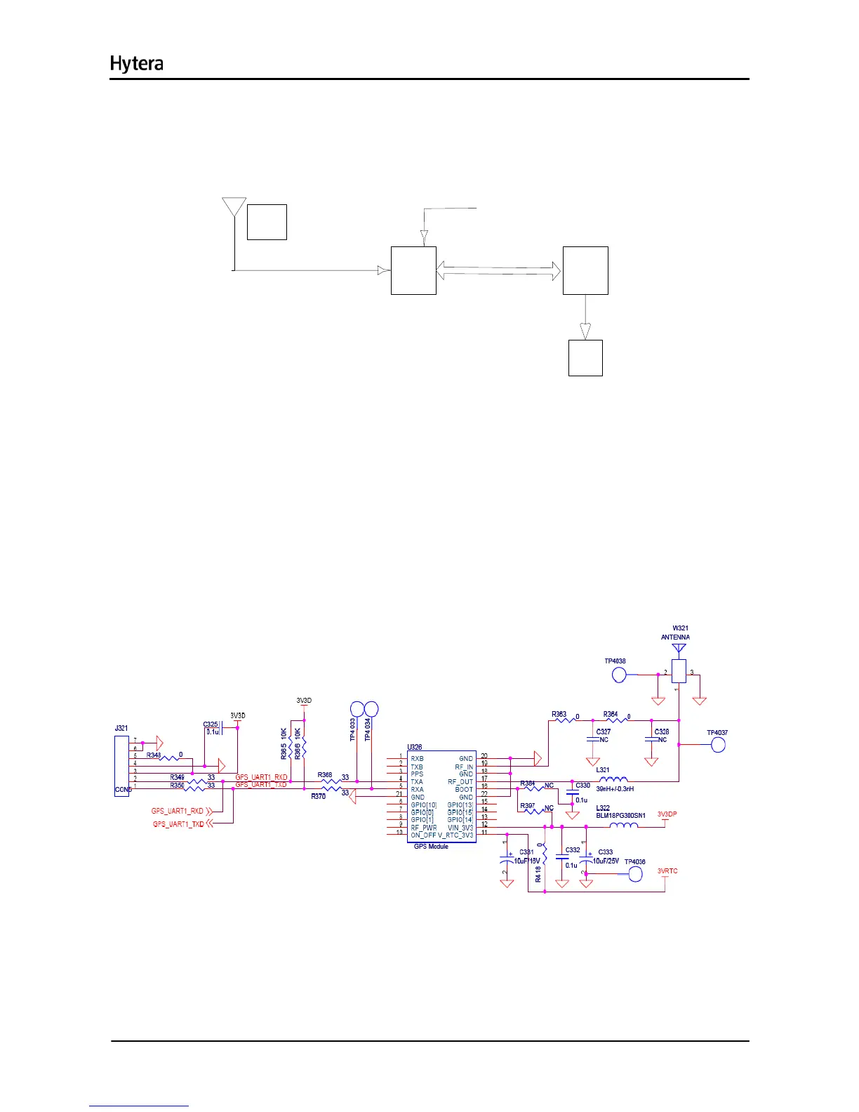
8.1 Circuit Description
GPS
module
OMAP
UART
GPS
Antenna
LCD
Power
RE B-1315LPx
Figure 8-1 Diagram of GPS Circuit
GPS positioning information can be acquired via the programmed GPS key on the front panel. The GPS
function is realized via REB-1315LPx module, which integrates GPS baseband processor circuits.
The GPS signal (1.57542GHz), received via the GPS active antenna (with a built-in LNA), goes to the
GPS module for processing, and then enters U302 via the UART port. Meanwhile, U302 sends control
command to the GPS module and forwards processed GPS information to the LCD.
8.2 Schematic Diagram
Figure 8-2 GPS Schematic Diagram
20

 Loading...