Service Manual
The PLL synthesizer that consists of the reference oscillator (X100), PLL IC (U100) and VCO, is utilized
to supply excitation signal source to the transmitter, and local oscillator signal to the receiver.
11.3.2 Reference Oscillator
X100 is a 19.2MHz TCXO, and its reference frequency is calibrated by the digital-to-analog converter
(U500) for accuracy.
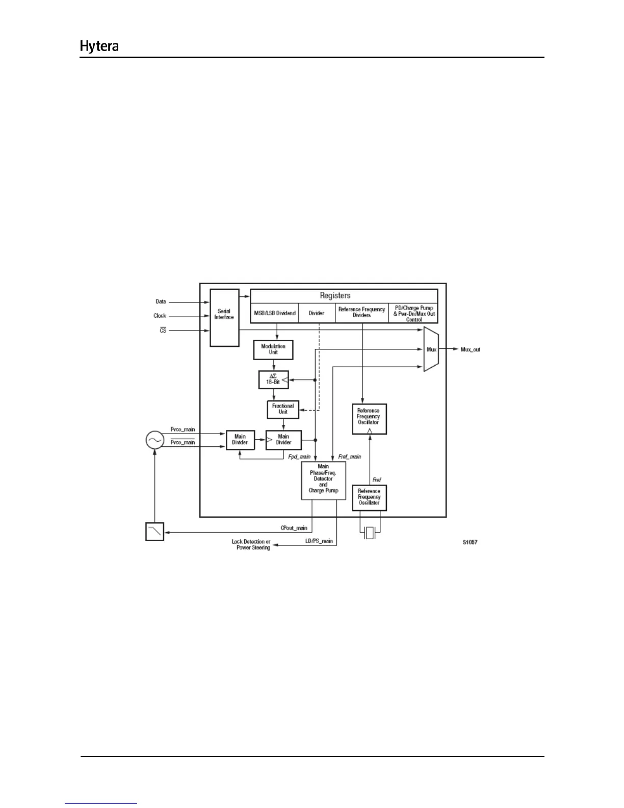
11.3.3 PLL IC
The PLL IC (U100) is a fractional frequency divider. The logic IC U101 and U102 work with the PLL IC
(U100) to achieve locking.
Figure 11-4 Diagram of PLL IC
The 19.2MHz frequency generated by the reference oscillator goes into the PLL IC for division,
generating the reference frequency. Meanwhile, the frequency generated by VCO goes into PLL IC
(U100) for frequency division. The resulting frequency will be compared with the reference frequency in
terms of phase difference in the phase detector. After comparison, the resulting frequency is converted
to CV voltage via the loop filter, to control and lock the frequency.
11.3.4 VCO
The VCO is composed of transistors (Q100, Q103, Q106 and Q110), varactors and four Colpitts
31

 Loading...