Do you have a question about the Hyundai HSH-P091NDC and is the answer not in the manual?
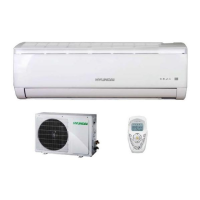
Lists key performance metrics and physical attributes of the air conditioner unit.
Lists and describes the primary functions and features available in the control system.
Details the available operating modes (Cooling, Heat, Dry, Fan) and their combinations.
Provides procedures for checking individual components like motors and compressors.
Details the process and tools for checking the refrigerant system's status.
Procedures for testing compressor resistance, common issues, and assembly notes.
Visual diagram showing the assembly of the outdoor unit with numbered parts.
Detailed table listing part numbers, Chinese descriptions, English descriptions, and quantities.
Provides guidance on choosing suitable locations for both indoor and outdoor units.
Detailed steps and torque specifications for connecting the refrigerant pipes.
Instructions for correctly connecting the power supply and grounding wires.
Steps for performing initial operational tests and checking performance after installation.
Details the purpose and operation of each button on the remote control.
Specifies the optimal environmental conditions for the air conditioner's operation.
Guidelines for safe installation and operation to prevent hazards.
Tips for ensuring the air conditioner operates at peak efficiency.
Important warnings regarding power supply and cleaning procedures.
Critical safety warnings about potential hazards during operation and maintenance.
Procedures for maintaining the air conditioner, including cleaning and troubleshooting.
Table listing common failure types and recommended solutions.
Steps for removing, cleaning, and reinstalling the air filter.
Wiring diagram for the indoor unit's electrical components.
Detailed schematic of the indoor unit's electrical connections.
Wiring diagram for the outdoor unit's electrical components.
Detailed schematic of the outdoor unit's electrical connections.
Essential preliminary checks for troubleshooting, including voltage and connections.
Explains cooling mode operation, temperature control, and fan speed settings.
Explains heating mode operation, temperature control, and fan speed settings.
Details the sleep mode operation, including automatic temperature adjustments.
Explains the setup and operation of timer functions for starting and stopping the unit.
Lists fault codes and their corresponding display indications for troubleshooting.
Detailed circuit diagram of the main control board (PCB).
Provides overall dimensions and installation clearances for the indoor unit.
Provides overall dimensions and installation clearances for the outdoor unit.
Diagrams illustrating the cooling cycle for a cooling-only air conditioner.
Diagrams illustrating cooling and heating cycles for a heat pump unit.
Shows the refrigerant flow and state changes during heating operation.
Illustrates the thermodynamic cycle of refrigerant during heating.
Step-by-step guide for disassembling the indoor unit's main components.
Detailed steps for disassembling various parts of the indoor unit.
Instructions for taking apart the indoor unit, covering panel and component removal.
Step-by-step guide for disassembling the outdoor unit's main components.
Instructions for disassembling the outdoor unit, including fan, motor, and valves.
Lists error codes and their corresponding indications on the outdoor and indoor units.
A graphical troubleshooting guide to systematically diagnose and resolve system problems.
| Cooling Capacity | 9000 BTU/h |
|---|---|
| Type | Split Type |
| Power Supply | 220-240V, 50Hz |
| Energy Efficiency Ratio (EER) | 3.21 |
| Coefficient of Performance (COP) | 3.61 |
| Refrigerant | R410A |
| Noise Level (Indoor) | 38 dB(A) |
| Weight (Indoor Unit) | 8 kg |
| Noise Level (Outdoor) | 50 dB(A) |
| Dimensions (Outdoor Unit) | 700 x 245 x 540 mm |
| Heating Capacity | 9500 BTU/h |