Second Part
INSTRUCTIONS
T()R USE
OF
TI{E ANAI.YSER
PAIENIED MODET I.C.E. 680
R
T0 use the I.C.E. Model
680 R Analyser correctly
and thus avoid
possible
err0rs in operation,
it is essential t0 carefully
follow the !nstructions
given
herewith.
For any measurement
it is very important
to
plug
the leads into
the appropriate
sockets
comp letely.
ln the
SUPIRTESTER 680
R
the
five common sockets
for the different measurement
fields,
namely
available for different ranges, have
a double line f0r
better indentificati0n
and with
the exception of
the commcn for the
ohmmetric measurements,
are located left
0f the
switch that doubles the
ammetric and voltmetric
ranges. Before
effecting any measurement,
make sure that the instrument
pointer
is exactly
on zer0 by rotatlng,
with the
aid 0f a
screwdriver, the small
button with a slot
situated on the casing of
the instrunrent
bel0v/
the instrument
panel.
All measurements
with
direct current must be
read on the biack
scale
and ihose with
alternating cirrrent on
the red
scale.
The
same applies
to the whiie
and red wording
at
the
side of the relative
sockets.
ln the
schematic circuit diagrams
illustrated in
the following the scale
to be exaniined for
the correct
reading is marked
by
a
much heayiet
line
as
compared
with the others.
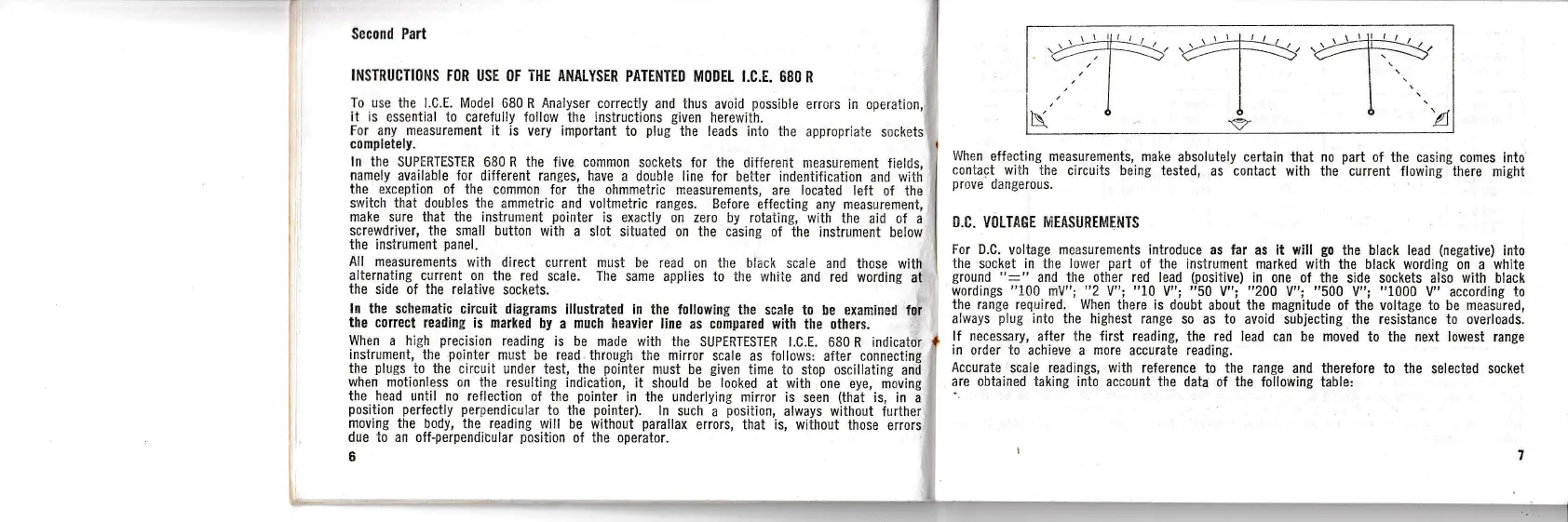
When a hi.gh
precision
reading is be
made wiih the
SUPERTESTER l.C.E. 680
R indicator
I
instrument, the
pointer
must be read
ihrough the mirror
scale as follows:
after cgnnecting
the
plugs
t0 the
circuit undor test, the
pointer
nlust be
given
time to stop oscillating
and
when motionless on the
resulting indication,
it should be looked
at with 0ne
eye, moving
the head until no reflection
of the
pointer
in the underlying mirror
is seen
(that
is, in
a
position
perfectiy perpendicular
t0 the
pointer).
ln such
a
positi0n,
always without
further
moving the b0dy, the reading
wi!l be
without
parallax
errors, that is, without
those
eri.ors
due t0 an off-perpendicular
p0siti0n
of the operaior.
b
When
effecting measurements, make
absolutely certain that
n0
part
0f the casing
comes into
c0ntact with
the circuits being
tested, as contact
with the current fl0wing there
might
prove
dangerous.
O.C.
VOLTAGE MEASUREMEi.ITS
for D-C.
voltage measurements introduce as ,ar as it will
g0
the black lead
(negative)
into
the
socket
in
the
Iower
part
of the instrument marked
w;th the black wording
on a
white
ground
":"
and the other red lead
(positive)
in one of the
side sockets als0 with black
wordings
"100
rnV";
"2
V";
"10
V";
"50
V";
"200
V";
"500
V";
"1000
V" according to
the range
required. When there is doubt
about the magnitude of the
voltage
to
be
measured,
always
plug
into the highest range
s0 as to arroid subjecting the resistance to overloads.
If necessary,
after
the first
reading, the red Iead can
be
moved
to the next lowest range
in order to
achieve a
more
accurate reading.
Accurate
scaie readings, with reference to the range
and therefore to
the selected socket
are obtained
taking into account the data
of
the
following table:
 Loading...