Do you have a question about the Ibiza sound AMP Series and is the answer not in the manual?
Avoid placing sensitive equipment near the unit due to strong magnetic fields. The field has strongest spots above and below.
Do not remove covers; no user serviceable parts inside. Refer servicing to qualified personnel.
To reduce the risk of electric shock, do not expose this equipment to rain or moisture.
Explains icons for important operating or maintenance instructions and risk of electric shock.
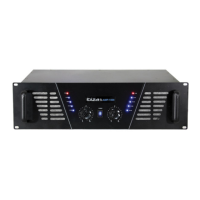
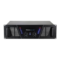
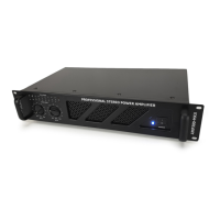
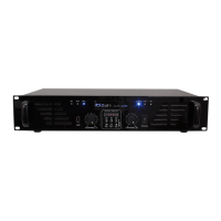
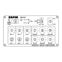
Diagram and labels for the front panel of the AMP300 model, showing controls and indicators.
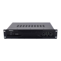
Diagram and labels for the rear panel of the AMP300 model, showing connections and power input.
The power switch with an integrated LED indicator for power status.
Input gain control to attenuate the input signal sent to the amplifier channels.
Shows the master output level of the amplifier.
Jack sockets connected in parallel to RCA connectors for linking multiple amplifiers.
Binding posts or XLR/Jack for connecting speakers, minimum load 4 Ohms.
Connection point for the mains power supply.
Ensure the mains outlet is earthed and complies with safety regulations.
Verify the mains voltage corresponds to the supply voltage indicated on the rear panel.
Always switch on the amplifier last and switch it off first to avoid noise.
Install in a well-ventilated place to avoid malfunction and fire risk; ensure airflow is not obstructed.
Switch off all units before connecting, use high-quality leads, handle cables with care.
Install away from industrial/high frequency radiations, radio, TV, or mobile phones.
Connect grounds to a central point (mixer) to avoid ground loops and improve sound quality.
Describes amplifier and speaker outputs, and effect unit outputs.
Describes line signal inputs from instruments like keyboards, samplers, recorders.
| Brand | Ibiza sound |
|---|---|
| Model | AMP Series |
| Category | Amplifier |
| Language | English |