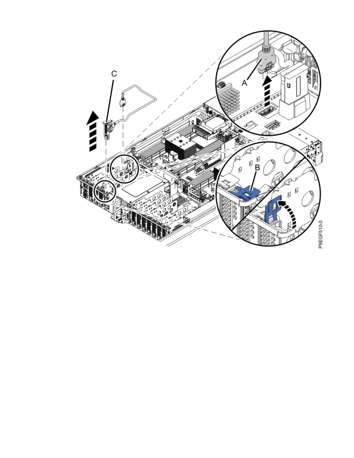
Figure 14. Removing the rear USB cable
c) Lift the rear USB cable out of the system.
d) Place the rear USB cable on an appropriate ESD surface.
5. Disconnect the front USB cable from the system backplane:
a) Pressing the latch release on the connector, disconnect the front USB cable from the system
backplane as shown in the following gure. The USB connector on the system backplane has the
USB port symbol with an arrow pointing to the front of the system.
b) Unfasten the cable from the hook and loop fasteners that secure the cable to the right side of the
chassis.
c) Route the cable over the side of the system and out of the way to provide clearance for removing
the backplane. See the following gure.
Removing and replacing the system backplane in the 5105-22E, 9008-22L, 9009-22A, 9009-22G, 9223-22H,
or 9223-22S 17
 Loading...